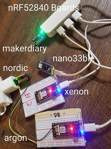
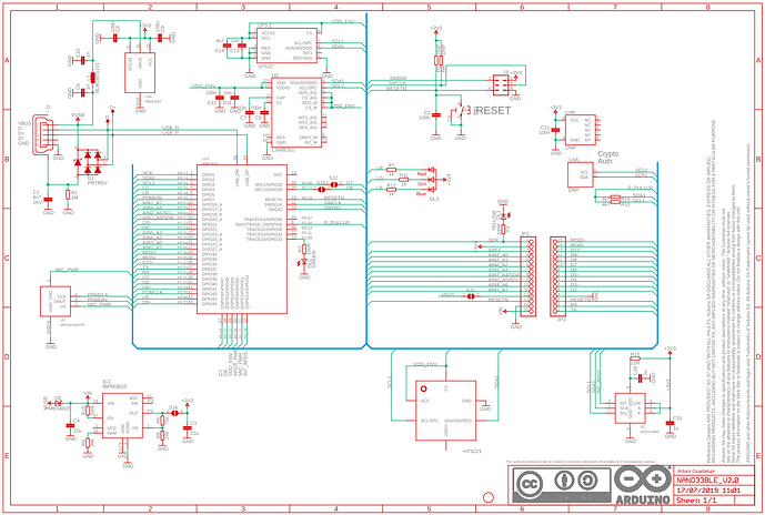
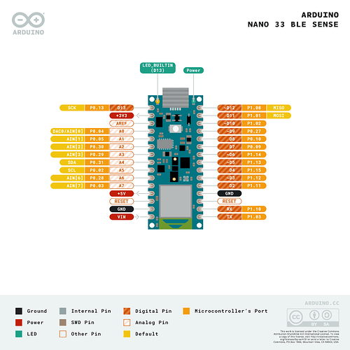
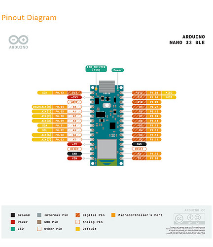
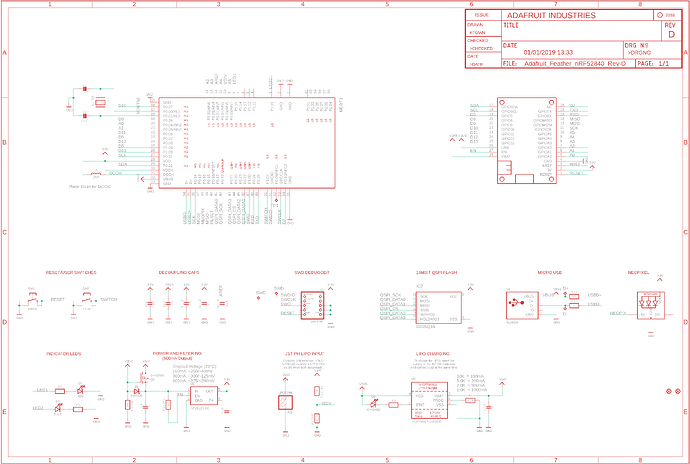
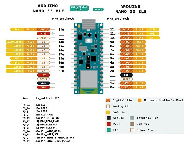
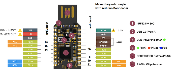
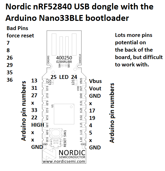
So I found this file in the arduino github and it looks like for the arduino nano 33 BLE that all Port0 and port1 pins are pre-defined with constants like “P0_13” for pin 13 which is the arduino built in LED. I just replaced 13 wtih P0_13 and it compiled. Hopefully that means every pin can be accessed from code by simply using the Pin definition. P1_7 etc. Looks like you could also use codes like p0 up to p47 but that is a data abstraction that adds confusion. I think I will just use pin labels like P1_12 etc.
typedef enum {
PinDef(0 , 0), // P0_0 = 0...
PinDef(0 , 1),
PinDef(0 , 2),
PinDef(0 , 3),
PinDef(0 , 4),
PinDef(0 , 5),
PinDef(0 , 6),
PinDef(0 , 7),
PinDef(0 , 8),
PinDef(0 , 9),
PinDef(0 , 10),
PinDef(0 , 11),
PinDef(0 , 12),
PinDef(0 , 13),
PinDef(0 , 14),
PinDef(0 , 15),
PinDef(0 , 16),
PinDef(0 , 17),
PinDef(0 , 18),
PinDef(0 , 19),
PinDef(0 , 20),
PinDef(0 , 21),
PinDef(0 , 22),
PinDef(0 , 23),
PinDef(0 , 24),
PinDef(0 , 25),
PinDef(0 , 26),
PinDef(0 , 27),
PinDef(0 , 28),
PinDef(0 , 29),
PinDef(0 , 30),
PinDef(0 , 31),

PinDef(1 , 0), //P1_1 = 32...
PinDef(1 , 1),
PinDef(1 , 2),
PinDef(1 , 3),
PinDef(1 , 4),
PinDef(1 , 5),
PinDef(1 , 6),
PinDef(1 , 7),
PinDef(1 , 8),
PinDef(1 , 9),
PinDef(1 , 10),
PinDef(1 , 11),
PinDef(1 , 12),
PinDef(1 , 13),
PinDef(1 , 14),
PinDef(1 , 15),

// Port0
p0  = P0_0,
p1  = P0_1,
p2  = P0_2,
p3  = P0_3,
p4  = P0_4,
p5  = P0_5,
p6  = P0_6,
p7  = P0_7,
p8  = P0_8,
p9  = P0_9,
p10 = P0_10,
p11 = P0_11,
p12 = P0_12,
p13 = P0_13,
p14 = P0_14,
p15 = P0_15,
p16 = P0_16,
p17 = P0_17,
p18 = P0_18,
p19 = P0_19,
p20 = P0_20,
p21 = P0_21,
p22 = P0_22,
p23 = P0_23,
p24 = P0_24,
p25 = P0_25,
p26 = P0_26,
p27 = P0_27,
p28 = P0_28,
p29 = P0_29,
p30 = P0_30,
p31 = P0_31,

// Port1
p32 = P1_0,
p33 = P1_1,
p34 = P1_2,
p35 = P1_3,
p36 = P1_4,
p37 = P1_5,
p38 = P1_6,
p39 = P1_7,
p40 = P1_8,
p41 = P1_9,
p42 = P1_10,
p43 = P1_11,
p44 = P1_12,
p45 = P1_13,
p46 = P1_14,
p47 = P1_15,
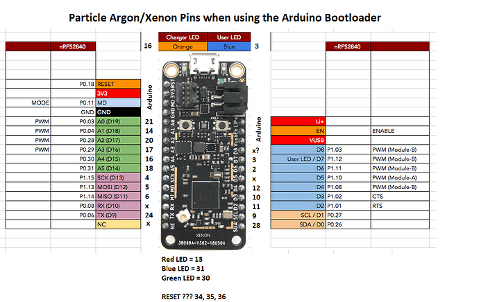
I also found this bit of definitions for the particle Argon which describes RGBred as NRF_PORT_0, 13 which on the arduino should simple be P0_13
Just need to start testing things out. Can’t seem to find pin assignments for the Nordic nRF52840 USB dongle or the makerdiary dongle but that should just take some time.
static Hal_Pin_Info s_pin_map[TOTAL_PINS] = {
/* D0 / SDA      - 00 */ { NRF_PORT_0, 26, PIN_MODE_NONE, PF_NONE, ADC_CHANNEL_NONE, PWM_INSTANCE_NONE, PWM_CHANNEL_NONE, 8, EXTI_CHANNEL_NONE},
/* D1 / SCL      - 01 */ { NRF_PORT_0, 27, PIN_MODE_NONE, PF_NONE, ADC_CHANNEL_NONE, PWM_INSTANCE_NONE, PWM_CHANNEL_NONE, 8, EXTI_CHANNEL_NONE},
/* D2 /          - 02 */ { NRF_PORT_1, 1,  PIN_MODE_NONE, PF_NONE, ADC_CHANNEL_NONE, 3,                 0,                8, EXTI_CHANNEL_NONE},
/* D3 /          - 03 */ { NRF_PORT_1, 2,  PIN_MODE_NONE, PF_NONE, ADC_CHANNEL_NONE, 3,                 1,                8, EXTI_CHANNEL_NONE},
/* D4            - 04 */ { NRF_PORT_1, 8,  PIN_MODE_NONE, PF_NONE, ADC_CHANNEL_NONE, 1,                 0,                8, EXTI_CHANNEL_NONE},
/* D5            - 05 */ { NRF_PORT_1, 10, PIN_MODE_NONE, PF_NONE, ADC_CHANNEL_NONE, 1,                 1,                8, EXTI_CHANNEL_NONE},
/* D6            - 06 */ { NRF_PORT_1, 11, PIN_MODE_NONE, PF_NONE, ADC_CHANNEL_NONE, 1,                 2,                8, EXTI_CHANNEL_NONE},
/* D7            - 07 */ { NRF_PORT_1, 12, PIN_MODE_NONE, PF_NONE, ADC_CHANNEL_NONE, 0,                 0,                8, EXTI_CHANNEL_NONE},
/* D8            - 08 */ { NRF_PORT_1, 3,  PIN_MODE_NONE, PF_NONE, ADC_CHANNEL_NONE, 1,                 3,                8, EXTI_CHANNEL_NONE},
/* D9            - 09 */ { NRF_PORT_0, 6,  PIN_MODE_NONE, PF_NONE, ADC_CHANNEL_NONE, PWM_INSTANCE_NONE, PWM_CHANNEL_NONE, 8, EXTI_CHANNEL_NONE},
/* D10           - 10 */ { NRF_PORT_0, 8,  PIN_MODE_NONE, PF_NONE, ADC_CHANNEL_NONE, PWM_INSTANCE_NONE, PWM_CHANNEL_NONE, 8, EXTI_CHANNEL_NONE},
/* D11           - 11 */ { NRF_PORT_1, 14, PIN_MODE_NONE, PF_NONE, ADC_CHANNEL_NONE, PWM_INSTANCE_NONE, PWM_CHANNEL_NONE, 8, EXTI_CHANNEL_NONE},
/* D12           - 12 */ { NRF_PORT_1, 13, PIN_MODE_NONE, PF_NONE, ADC_CHANNEL_NONE, PWM_INSTANCE_NONE, PWM_CHANNEL_NONE, 8, EXTI_CHANNEL_NONE},
/* D13           - 13 */ { NRF_PORT_1, 15, PIN_MODE_NONE, PF_NONE, ADC_CHANNEL_NONE, PWM_INSTANCE_NONE, PWM_CHANNEL_NONE, 8, EXTI_CHANNEL_NONE},
/* A5            - 14 */ { NRF_PORT_0, 31, PIN_MODE_NONE, PF_NONE, 7,                3,                 2,                8, EXTI_CHANNEL_NONE},
/* A4            - 15 */ { NRF_PORT_0, 30, PIN_MODE_NONE, PF_NONE, 6,                3,                 3,                8, EXTI_CHANNEL_NONE},
/* A3            - 16 */ { NRF_PORT_0, 29, PIN_MODE_NONE, PF_NONE, 5,                2,                 0,                8, EXTI_CHANNEL_NONE},
/* A2            - 17 */ { NRF_PORT_0, 28, PIN_MODE_NONE, PF_NONE, 4,                2,                 1,                8, EXTI_CHANNEL_NONE},
/* A1            - 18 */ { NRF_PORT_0, 4,  PIN_MODE_NONE, PF_NONE, 2,                2,                 2,                8, EXTI_CHANNEL_NONE},
/* A0            - 19 */ { NRF_PORT_0, 3,  PIN_MODE_NONE, PF_NONE, 1,                2,                 3,                8, EXTI_CHANNEL_NONE},
/* MODE BUTTON   - 20 */ { NRF_PORT_0, 11, PIN_MODE_NONE, PF_NONE, ADC_CHANNEL_NONE, PWM_INSTANCE_NONE, PWM_CHANNEL_NONE, 8, EXTI_CHANNEL_NONE},
/* RGBR          - 21 */ { NRF_PORT_0, 13, PIN_MODE_NONE, PF_NONE, ADC_CHANNEL_NONE, 0,                 1,                8, EXTI_CHANNEL_NONE},
/* RGBG          - 22 */ { NRF_PORT_0, 14, PIN_MODE_NONE, PF_NONE, ADC_CHANNEL_NONE, 0,                 2,                8, EXTI_CHANNEL_NONE},
/* RGBB          - 23 */ { NRF_PORT_0, 15, PIN_MODE_NONE, PF_NONE, ADC_CHANNEL_NONE, 0,                 3,                8, EXTI_CHANNEL_NONE},
/* TX1           - 24 */ { NRF_PORT_1, 5,  PIN_MODE_NONE, PF_NONE, ADC_CHANNEL_NONE, PWM_INSTANCE_NONE, PWM_CHANNEL_NONE, 8, EXTI_CHANNEL_NONE},
/* RX1           - 25 */ { NRF_PORT_1, 4,  PIN_MODE_NONE, PF_NONE, ADC_CHANNEL_NONE, PWM_INSTANCE_NONE, PWM_CHANNEL_NONE, 8, EXTI_CHANNEL_NONE},
/* CTS1          - 26 */ { NRF_PORT_1, 6,  PIN_MODE_NONE, PF_NONE, ADC_CHANNEL_NONE, PWM_INSTANCE_NONE, PWM_CHANNEL_NONE, 8, EXTI_CHANNEL_NONE},
/* RTS1          - 27 */ { NRF_PORT_1, 7,  PIN_MODE_NONE, PF_NONE, ADC_CHANNEL_NONE, PWM_INSTANCE_NONE, PWM_CHANNEL_NONE, 8, EXTI_CHANNEL_NONE},
/* ESPBOOT       - 28 */ { NRF_PORT_0, 16, PIN_MODE_NONE, PF_NONE, ADC_CHANNEL_NONE, PWM_INSTANCE_NONE, PWM_CHANNEL_NONE, 8, EXTI_CHANNEL_NONE},
/* ESPEN         - 29 */ { NRF_PORT_0, 24, PIN_MODE_NONE, PF_NONE, ADC_CHANNEL_NONE, PWM_INSTANCE_NONE, PWM_CHANNEL_NONE, 8, EXTI_CHANNEL_NONE},
/* HWAKE         - 30 */ { NRF_PORT_0, 7,  PIN_MODE_NONE, PF_NONE, ADC_CHANNEL_NONE, PWM_INSTANCE_NONE, PWM_CHANNEL_NONE, 8, EXTI_CHANNEL_NONE},
/* ANTSW1        - 31 */ { NRF_PORT_0, 2,  PIN_MODE_NONE, PF_NONE, ADC_CHANNEL_NONE, PWM_INSTANCE_NONE, PWM_CHANNEL_NONE, 8, EXTI_CHANNEL_NONE},
/* ANTSW2        - 32 */ { NRF_PORT_0, 25, PIN_MODE_NONE, PF_NONE, ADC_CHANNEL_NONE, PWM_INSTANCE_NONE, PWM_CHANNEL_NONE, 8, EXTI_CHANNEL_NONE},
/* BATT          - 33 */ { NRF_PORT_0, 5,  PIN_MODE_NONE, PF_NONE, 3,                PWM_INSTANCE_NONE, PWM_CHANNEL_NONE, 8, EXTI_CHANNEL_NONE},
/* PWR           - 34 */ { NRF_PORT_0, 12, PIN_MODE_NONE, PF_NONE, ADC_CHANNEL_NONE, PWM_INSTANCE_NONE, PWM_CHANNEL_NONE, 8, EXTI_CHANNEL_NONE},
/* CHG           - 35 */ { NRF_PORT_1, 9,  PIN_MODE_NONE, PF_NONE, ADC_CHANNEL_NONE, PWM_INSTANCE_NONE, PWM_CHANNEL_NONE, 8, EXTI_CHANNEL_NONE},
};
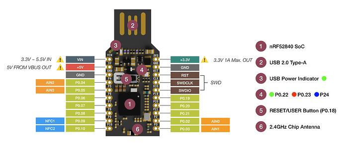
So here is the Makerdiary nRF52840 USB dongle pinout diagram. So “P0.10” on the diagram should be programmable with the Arduino IDE as “P0_10”
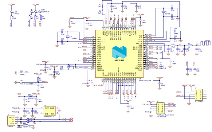
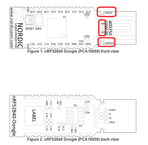
And for the Nordic nRF52840 USB dongle it looks like on this diagram the pins are labelled “0.11” which on Arduino would be “P0_11”
Got a lot of testing to do.
