@manuelbl you are correct for the other boards to do SWD I just needed the SWDCLK, SWDIO and GND. I got my bricked Nano 33 BLE working and managed to load the Nano 33 BLE bootloader onto both the Nordic nrf52840 Dongle and the Makerdiary dongle. The problem is DFU mode. I could not figure out how to get the makerdiary dongle go into dfu mode. I need to find the correct pin to work with the button. For the Nordic nrf52840 dongle there are pins that will do it but I managed to hold the main button while tapping the reset button and it worked. (Got that trick from an Adafruit site )
I also tested the Nano 33 BLE on visual studio using PlatformIO and it worked great.
The Xenon seems a bit flaky, working sometimes and not others. The Nordic Dongle with the Nano 33 BLE bootloader seems very stable. My only confusion now is how to change the built in LED. The Nordic dongle looks like it is doing absolutely nothing, but I know it works since my serial connection shows an A0 reading.
Any Arduino users who could help re-define LED_BUITLIN?
This is probably the default defining PIN 13 for most Arduino boards
#define LED_BUILTIN 13
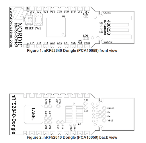
I found this info for the Nordic nrf52840 dongle. where SW1 and 2 are the two buttons, so LD1 and 2 should be the 2 very small on board LED’s. I don;t have any information for the main LED.
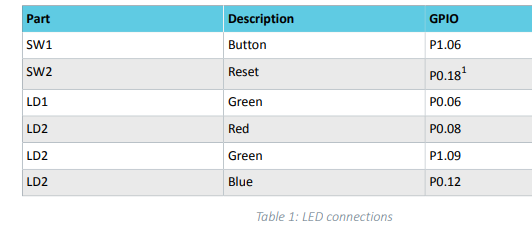
but trying 6, 8, 9 or 12 does not seem to work . Also P0.06 does not compile. This should be easy but I seem to be stumped.
#define LED_BUILTIN 8
compiles but does not effect either of the 2 onboard LED’s
.
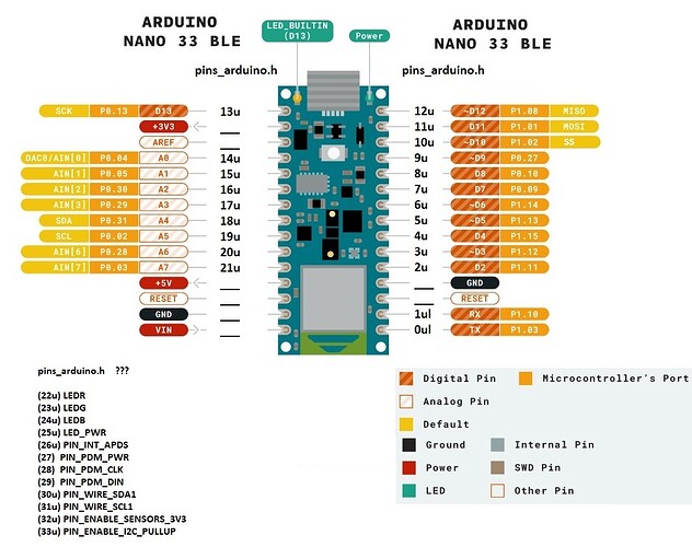
. So this is the nano33BLE pins_arduino.h file. That should give me something to work with.
#pragma once
#include "mbed_config.h"
#include <stdint.h>
#include <macros.h>

#ifndef __PINS_ARDUINO__
#define __PINS_ARDUINO__

// Frequency of the board main oscillator
#define VARIANT_MAINOSC (32768ul)

// Master clock frequency
#define VARIANT_MCK     (64000000ul)

// Pins
// ----

// Number of pins defined in PinDescription array
#ifdef __cplusplus
extern "C" unsigned int PINCOUNT_fn();
#endif
#define PINS_COUNT           (PINCOUNT_fn())
#define NUM_DIGITAL_PINS     (21u)
#define NUM_ANALOG_INPUTS    (7u)
#define NUM_ANALOG_OUTPUTS   (0u)

// LEDs
// ----
#define PIN_LED     (13u)
#define LED_BUILTIN PIN_LED
#define LEDR        (22u)
#define LEDG        (23u)
#define LEDB        (24u)
#define LED_PWR     (25u)

// Analog pins
// -----------
#define PIN_A0 (14u)
#define PIN_A1 (15u)
#define PIN_A2 (16u)
#define PIN_A3 (17u)
#define PIN_A4 (18u)
#define PIN_A5 (19u)
#define PIN_A6 (20u)
#define PIN_A7 (21u)
static const uint8_t A0  = PIN_A0;
static const uint8_t A1  = PIN_A1;
static const uint8_t A2  = PIN_A2;
static const uint8_t A3  = PIN_A3;
static const uint8_t A4  = PIN_A4;
static const uint8_t A5  = PIN_A5;
static const uint8_t A6  = PIN_A6;
static const uint8_t A7  = PIN_A7;
#define ADC_RESOLUTION 12

/*
 * Serial interfaces
 */
// Serial (EDBG)
#define PIN_SERIAL_RX (1ul)
#define PIN_SERIAL_TX (0ul)

// SPI
#define PIN_SPI_MISO  (12u)
#define PIN_SPI_MOSI  (11u)
#define PIN_SPI_SCK   (13u)
#define PIN_SPI_SS    (10u)

static const uint8_t SS   = PIN_SPI_SS;   // SPI Slave SS not used. Set here only for reference.
static const uint8_t MOSI = PIN_SPI_MOSI;
static const uint8_t MISO = PIN_SPI_MISO;
static const uint8_t SCK  = PIN_SPI_SCK;

// Wire
#define PIN_WIRE_SDA        (18u)
#define PIN_WIRE_SCL        (19u)

#define PIN_WIRE_SDA1       (30u)
#define PIN_WIRE_SCL1       (31u)

#define PIN_ENABLE_SENSORS_3V3     (32u)
#define PIN_ENABLE_I2C_PULLUP      (33u)

#define PIN_INT_APDS (26u)

// PDM Interfaces
// ---------------
#define PIN_PDM_PWR	 (27)
#define PIN_PDM_CLK	 (28)
#define PIN_PDM_DIN	 (29)

// These serial port names are intended to allow libraries and architecture-neutral
// sketches to automatically default to the correct port name for a particular type
// of use.  For example, a GPS module would normally connect to SERIAL_PORT_HARDWARE_OPEN,
// the first hardware serial port whose RX/TX pins are not dedicated to another use.
//
// SERIAL_PORT_MONITOR        Port which normally prints to the Arduino Serial Monitor
//
// SERIAL_PORT_USBVIRTUAL     Port which is USB virtual serial
//
// SERIAL_PORT_LINUXBRIDGE    Port which connects to a Linux system via Bridge library
//
// SERIAL_PORT_HARDWARE       Hardware serial port, physical RX & TX pins.
//
// SERIAL_PORT_HARDWARE_OPEN  Hardware serial ports which are open for use.  Their RX & TX
//                            pins are NOT connected to anything by default.
#define SERIAL_PORT_USBVIRTUAL      SerialUSB
#define SERIAL_PORT_MONITOR         SerialUSB
#define SERIAL_PORT_HARDWARE        Serial1
#define SERIAL_PORT_HARDWARE_OPEN   Serial1


// Mbed specific defines
#define SERIAL_HOWMANY		1
#define SERIAL1_TX			(digitalPinToPinName(PIN_SERIAL_TX))
#define SERIAL1_RX			(digitalPinToPinName(PIN_SERIAL_RX))

#define SERIAL_CDC			1
#define HAS_UNIQUE_ISERIAL_DESCRIPTOR
#define BOARD_VENDORID		0x2341
#define BOARD_PRODUCTID		0x805a
#define BOARD_NAME			"Nano 33 BLE"

#define DFU_MAGIC_SERIAL_ONLY_RESET   0xb0

#define I2C_SDA				(digitalPinToPinName(PIN_WIRE_SDA))
#define I2C_SCL				(digitalPinToPinName(PIN_WIRE_SCL))
#define I2C_SDA1			(digitalPinToPinName(PIN_WIRE_SDA1))
#define I2C_SCL1			(digitalPinToPinName(PIN_WIRE_SCL1))

#define SPI_MISO			(digitalPinToPinName(PIN_SPI_MISO))
#define SPI_MOSI			(digitalPinToPinName(PIN_SPI_MOSI))
#define SPI_SCK				(digitalPinToPinName(PIN_SPI_SCK))

#define digitalPinToPort(P)		(digitalPinToPinName(P)/32)

uint8_t getUniqueSerialNumber(uint8_t* name);
void _ontouch1200bps_();

#endif //__PINS_ARDUINO__
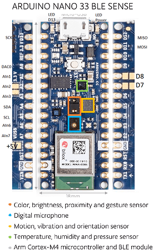
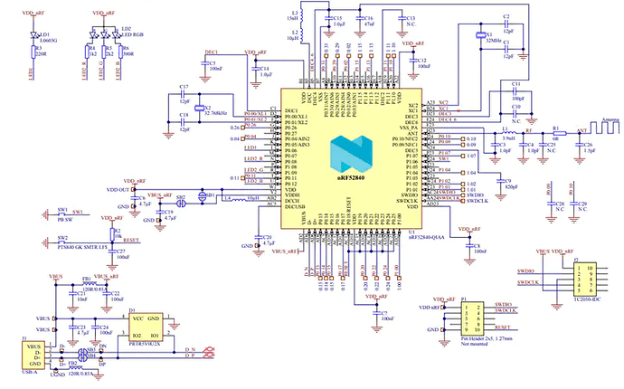
Also found a couple of datasheet/Diagrams:
Note: Strange that none of these have any of the numbers that the pins_arduino.h file uses. I might have to make my own diagrams listing the (13u) etc locations.
Nano 33 BLE Sense
.
.
.
Nordic nrf52840
