I have gotten a new board, a SKR 1.4. I already have a SKR 1.3 and have Marlin 2.0 installed on it. After a handful of firmware flashes changing some configuration options in Marlin the SKR 1.4 seems to be dead.
On my SKR 1.3 I have managed to also get it to a state in which it wouldn’t connect to my PC. However, a known ‘good’ Smoothieware binary got it to connect again.
The SKR 1.4 doesn’t show up in my Device Manager on Windows and the bootloader also doesn’t flash/load the binary from the Sd card. It is the same binary I use on the SKR 1.3 and it doesn’t rename it to a firmware.cur file.
As I just got this board 2 days ago, I wonder if there is an issue with the board or if there is something I can try before just sending it back as defective. For testing purposes I only had the x-motor and x-endstop connected.
Well this is not the Marlin or BigTreeTech SKR 3D printer forum so maybe these people can you help you better than we can here;
However, one piece of advice I can give you is to try and flash the board directly with a known good firmware, not via an SD update mechanism (that second-stage bootloader / updater burned on the chip might be broken or overwritten now), but via the chips internal bootloader (e.g., via the SWD or UART interface).
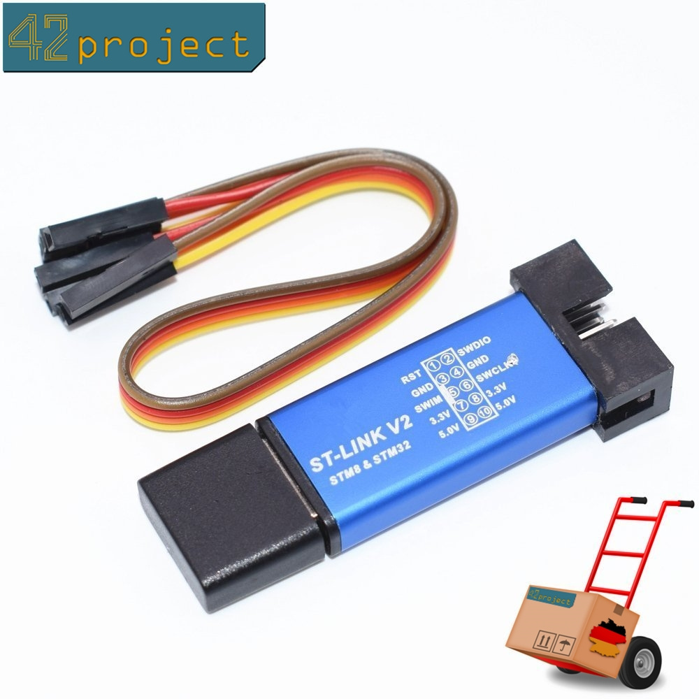
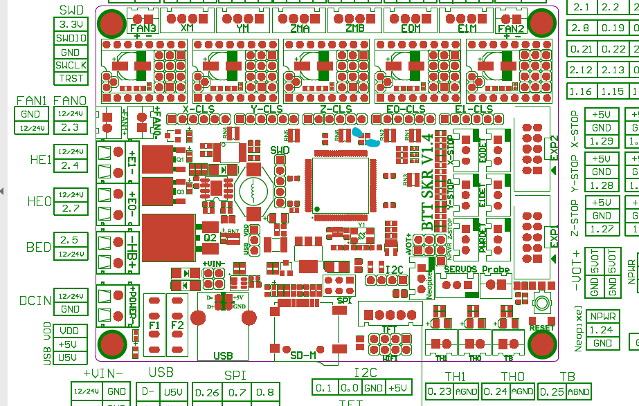
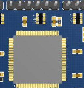
flashing-the-bootloader [smoothieware.org] does it via UART. But since the LPC1768 on the board has a Cortex M3 microprocessor, you can also flash it via SWD (SWCLK + SWDIO [+ GND]) and a cheap STLink V2 clone. According to the schematic this is very conveniently available via the J2 connector.
When using any PlatformIO project, e.g. Marlin, you can also set upload_protocol = stlink in the corresponding environment of the platformio.ini and it will try to use the STLink to flash the target board directly. If during flashing the chip doesn’t respond, either there’s a connection error or your chip is genuinely dead. But before trying these low-level methods, you don’t know whether the chip is dead or some component has failed as a result of the improper firmware flash.
Try to unplug the x endstops , or just connect the board to your PC with only the USB connected. Just switch the jumper to usb. For some reason mine in acting bricked when the x endstops is plugged it. Unplugged it’s normal
Installed STM32 ST-LINK Utility, connected the 4 wires to the SWD (J2) connector on the SKR 1.4. The Diode (labelled D4 on SKR 1.3) is illuminated when I connect the ST-Link Adapter. However I cannot get it to connect with ST-Link Utility. I tried all the different connection modes and also varied the connection frequency.
When I connect the STLink adapter to the ICSP header on my SKR1.3 I can at least get the status LED on the adapter to blink blue instead of red for a couple of seconds, the ST-Link utility also detects the target as 3.3v. However, the connection still fails.
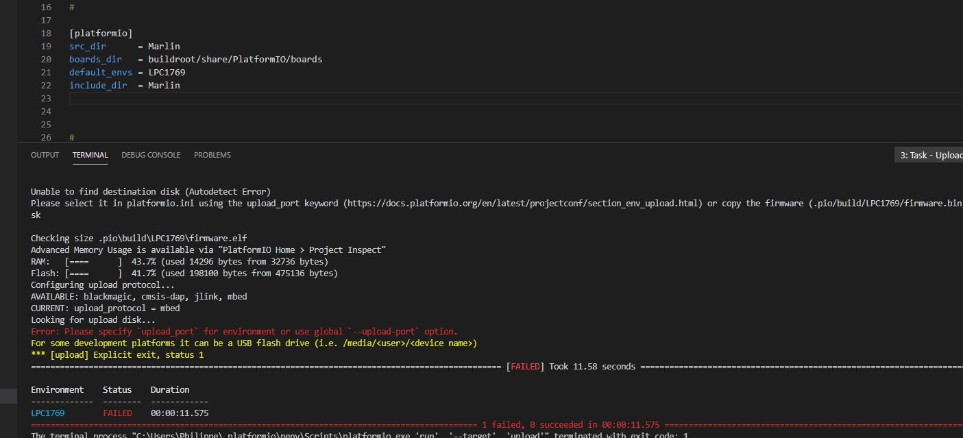
In PlatformIO I cannot select stlink as an upload_protocol as I get unknown upload protocol error. When I edit the config files for lpc1768 in my user config directory to add stlink to the supported upload protocols I still get unknown protocol.
I still have a FTDI 232H adapter, an original intel USB Blaster II and an Arrow USB Programmer. I mean some adapter has to somehow work…
Still an STLinkv2 should work, but not with the ST-Link utility, as that should only recognize STM32 chips. The STLink is however a universal SWD debugger (I’ve flashed a Realtek Ameba board with it) so it should have no problems.
Can you please do the following:
go to the folder C:\Users\<user>\.platformio\packages
if the folder tool-openocd is not there, download the latest version for your platform here into a newly created folder called tool-openocd.
open a terminal (like cmd.exe) and cd into the your tool-openocd directory (like cd C:\Users\<user>\.platformio\packages\tool-openocd)
try and use openocd to connect to the target LPC1768 chip using the command
If successfull you should see that it recognizes the chip and starts a GDB server.
E.g. when I tell it to connect to my Bluepill (STM32F103CB) board with a different config, output is like
xPack OpenOCD, 64-bit Open On-Chip Debugger 0.10.0+dev (2019-07-17-11:28)
Licensed under GNU GPL v2
For bug reports, read
        http://openocd.org/doc/doxygen/bugs.html
none separate

Info : auto-selecting first available session transport "hla_swd". To override use 'transport select <transport>'.
Info : The selected transport took over low-level target control. The results might differ compared to plain JTAG/SWD
Info : Listening on port 6666 for tcl connections
Info : Listening on port 4444 for telnet connections
Info : clock speed 1000 kHz
Info : STLINK V2J27S6 (API v2) VID:PID 0483:3748
Info : Target voltage: 3.247152
Info : stm32f1x.cpu: hardware has 6 breakpoints, 4 watchpoints
Info : Listening on port 3333 for gdb connections
If you can manually connect to the chip using openocd, we can start using a custom upload command (docs) to invoke openocd to flash the target.
Sorry for the confusion. The Diode which lights up is labelled as D4 on the actual PCB of the SKR 1.3. It is not labelled on the SKR 1.4. However, it will most likely have the same meaning. It is the same Diode which just signals that the board is powered.
I have tried connecting to the SKR 1.4 and my SKR 1.3.
SKR 1.4:
bin\openocd.exe -f scripts\interface\stlink.cfg -c "reset_config none separate" -f
scripts\target\lpc17xx.cfg
xPack OpenOCD, 64-bit Open On-Chip Debugger 0.10.0+dev (2019-07-17-11:28)
Licensed under GNU GPL v2
For bug reports, read
    http://openocd.org/doc/doxygen/bugs.html
none separate
Info : auto-selecting first available session transport "hla_swd". To override use 'transport select <transport>'.
 Info : The selected transport took over low-level target control. The results might differ compared to plain JTAG/SWD
Info : Listening on port 6666 for tcl connections
Info : Listening on port 4444 for telnet connections
Info : clock speed 10 kHz
Info : STLINK V2J29S7 (API v2) VID:PID 0483:3748
Info : Target voltage: 3.151845
Error: init mode failed (unable to connect to the target)
SKR 1.3:
 bin\openocd.exe -f scripts\interface\stlink.cfg -c "reset_config none separate" -f scripts\target\lpc17xx.cfg
xPack OpenOCD, 64-bit Open On-Chip Debugger 0.10.0+dev (2019-07-17-11:28)
Licensed under GNU GPL v2
For bug reports, read
    http://openocd.org/doc/doxygen/bugs.html
none separate

Info : auto-selecting first available session transport "hla_swd". To override use 'transport select <transport>'.
Info : The selected transport took over low-level target control. The results might differ compared to plain JTAG/SWD
Info : Listening on port 6666 for tcl connections
Info : Listening on port 4444 for telnet connections
Info : clock speed 10 kHz
Info : STLINK V2J29S7 (API v2) VID:PID 0483:3748
Info : Target voltage: 3.170871
Info : lpc17xx.cpu: hardware has 6 breakpoints, 4 watchpoints
Info : Listening on port 3333 for gdb connections
Alright so the LPC1768 on your SKR 1.3 is alive and well.
You can further verify this if you connect to the telnet interface (e.g. via ncat or telnet.exe) on the commandline (127.0.0.1 port 4444) and try to use commands for e.g. reading out the flash banks and dumping the flash content to a file (docs, reset halt, flash banks, flash info 0, flash read_bank 0 dump.bin,…). But this already strongly indicates that the MCU is alive and well.
But the SKR 1.4 doesn’t seem to be responding over the SWD interface . You can try a few things:
making sure that the TRST signal is connected as well to the STLink V2 (I think it’s NRST there)
omititing the -c "reset_config none separate" switch from the invocation
is the (not)RESET line permanently low? (holds the MCU in reset, should be high by default for “not in reset”)
disconnecting every external device from the motherboard, like motors, headbeds, LCDs and whatnot. The measured voltage 3.151845 seems a bit low for a 3.3V target, as if there’s a siginificant load / power draw in the system.
is the board externally powered? (I think the STLinkv2 will first try to measure the voltage on its VCC_TARGET pin, and if there’s no voltage present, will try to supply power - that may not be enough for the whole target motherboard; should use USB supply + the J15 jumper to VUSB maybe.)
using a multimeter, is the 3.3V rail of the board and especially on the microcontroller stable? (e.g. measurable via the C14 capacitor in the schematic)
does any chip get hot? are there burn marks on the PCB?
If the chip gets a proper power supply on all pins but still decides do nothing and not be connected to via its SWD interface, then the chip may be actually dead. These chips are listed for 4-5€ on ebay (lpc1768fbd100 LQFP100) so if you have a hot-air soldering gun and the skills, desoldering the chip and placing a new one might restore the motherboard.
All commands but this one worked. It returned connection lost.
SKR 1.4
I tried all steps but this one. I could not find the C14 capacitor in the schematic or the board. However, I measured the 3.3V pin on the SWD pin header and it showed 3.26V on my multimeter. Connecting external 5V USB power raised the chip voltage from 3.15V to 3.19V.
I got the board last week and it died within 30 minutes. I will just return it on Amazon… I also dislike that they removed a lot of the markings on v1.4 of the PCB. These labelled all the components and I don’t understand why they removed them. If I reorder a board I will get a second v1.3 instead.
Now I guess all that is left to do is figure out how to flash the SKR 1.3 via platformio (stlink)?
You should try to get binary dump of the firmware though for safety reasons, in case the bootloader is overwritten. What is the output of the previous commands about probing the flash banks?
A custom upload command can be set to invoke openocd with the previous flags plus a -c "program {<firmware elf>}; verify; reset", as seen in the docs.
flash read_bank 0 dump.bin
error reading to flash at address 0x00000000 at offset 0x00000000
Read error
jtag status contains invalid mode value - communication failure
Polling target lpc17xx.cpu failed, trying to reexamine
Examination failed, GDB will be halted. Polling again in 100ms
Previous state query failed, trying to reconnect
jtag status contains invalid mode value - communication failure
Polling target lpc17xx.cpu failed, trying to reexamine
Examination failed, GDB will be halted. Polling again in 300ms
Previous state query failed, trying to reconnect
After the connection is lost it is not possible to reconnect. Different reset configs have no effect. A power reset restores connectivity.
I had the same problem with my skr1.4 turboboard. I changed the lpc17xx-dfu-bootloader of triffid
(which flashes firmware.bin, renames it to firmware.cur and then boot). One of the changes was using pin P0_26 instead of pin P0_6 as SS pin. I flashed it with flashmagic and UART connection
to the SKR1.4 turbo. (I had to short the bootpin to GND.)
After that I can load new marlin firmware via a card reader shield module connected to the spi connector.
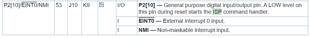
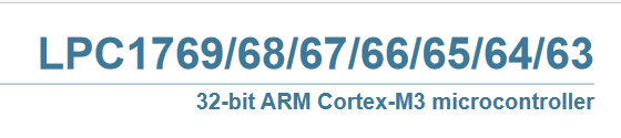
That’s weird from the pictures of the board I’ve seen, but it does not make a difference. You can see for yourself that the datasheet I linked to applies to
Thus the same pin is correct.
Have you found where you can access this pin easily on the motherboard?
So the signal ISP_BOOT is pulled-up to 3.3V via the 10kOhm resistor R28. Also capacitor C14 is right next to it.
The resistor should have the SMD code “103” on top for 10*10^3 = 10000 Ohm. Can you confirm that? Also make sure to only directly connect the side of the resistor to GND which is connected with the P2.10 pin, not the side that is connected to the 3.3V VDD side; that would create a short. Check with a multimeter to see which side of the resistor is connected to where (direct continuity to P2.10 with practically no resistance, 10k resistance to VCC in the other case)
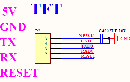
Note that to get to UART(0), you will have to connect a USB-UART adapter to where TXD0 and RXD0 is connected to. On that board that is
on the TFT screen connector P2. So if you have adapter hooked up that, bridged ISP_BOOT with GND, and then power up the board, the MCU should start up in ISP mode and you should be able to flash it with flashmagic.
However there’s also the possibility that the chip is simply dead…
thank you very much
your screens show me or was my mistake, I tried to flash by the SPI instead of the port TFT, I can now flash.
but the bootloader that I got here GitHub - Marsman1970/SKR-V1.3-Bootloader: KR V1.3 Bootloader may not be good, because I still cannot flash marlin via microSD