Dear All,
I have some problems with the configuration of the project. I have an esp32dev board and a FT2232H mini Module. I’ve linked them following the wiring connections at this link: _http://docs.platformio.org/en/latest/plus/debugging.html_
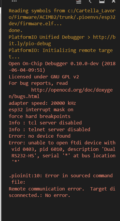
I have the driver for the FT2232H installed correctly on windows 10. When I try to execute the debug, I receive the following error:
Open On-Chip Debugger 0.10.0-dev (2018-06-04-09:51)
Licensed under GNU GPL v2
For bug reports, read OpenOCD: Bug Reporting
adapter speed: 20000 kHz
esp32 interrupt mask on
force hard breakpoints
Info : tcl server disabled
Info : telnet server disabled
Error: no device found
Error: unable to open ftdi device with vid 0403, pid 6010, description ‘Dual RS232-HS’, serial ‘’ at bus location '’
.pioinit:10: Error in sourced command file:
Remote communication error. Target disconnected.: No error.
I can’t understand why it couldn’t find the FTDI device. Any advice please?
Thank you so much.
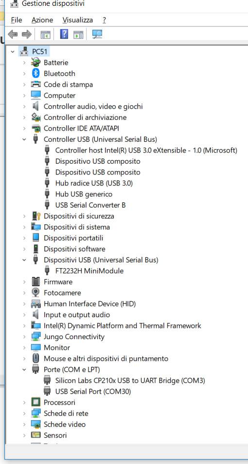
My os is windows 10. I think I’ve found some problems with FTDI drivers: the FT2232H mini module generates 4 USB-Serial converter instead of two. All of them have “usb migration problem”.
I’ve tried to reinstall the drivers with the latest one from FTDI website, but it doesn’t work. I am stuck because it does the same on other computers.
I’ve try to ask to FTDI support: lets see if they reply.
EDIT: I’ve found that you have to connect also V3V3 to VIO in the FT2232H Mini Module:
CN2, pins 1, 3 & 5 ----> CN2 pins 11 & 21 and CN3, pins 12 & 22
This solve the problem of the USB driver malfunction.
Anyway the debugger session doesn’t start: same messages as above: unable to open ftdi device…
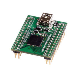
Are you sure that’s a FT2232 minimodule? Maybe you have FT4232 minimodule.
Please read what’s written on the module chip.
They look very similar.
FT2232 minimodule:
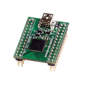
FT4232 minimodule:
The FT2232 is detected as 2 USB2Serial converter and FT4232 is detected as 4 USB2Serial converter
They also have different VID/PID.
FT2232: VID_0403&PID_6010
FT4232: VID_0403&PID_6011 (as i remember…)
Those values can be changed using FtProg but i think is easier to adapt the openocd settings to work with FT4232.
To edit the settings, go to
c:\Users[Your User].platformio\packages\tool-openocd-esp32\share\openocd\scripts\interface\ftdi\esp32_devkitj_v1.cfg
and change the PID to the one detected on windows device manager (ex. 6011)
As you can see, the debugger tell’s you exactly what’s the problem:
It can’t find a device with VID0403&PID6010 named “Dual RS232-HS”
That’s because your device is detected as “FT2232H-MiniModule” on device manager and may have a different VID&PID
Do you use the drivers from FTDI website?
Please post the VID/PID of the FT2232H-MiniModule from your device manager.
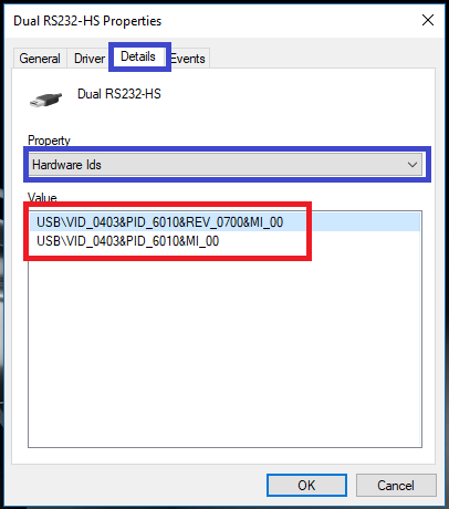
To find the VID/PID, go to device manager, right click on the device and select Properties->Details->Hardware Ids
The board says FT2232 on it so it doesn’t tie up with what the device is actually reporting. Surely debugging should be able to work with both devices. The only difference between them seems to be 2 or 4 channels?
Thanks. It’s slightly closer. I can now use minimodule by modifying mbftdi.cfg in .platformio\packages\tool-openocd-esp32\share\openocd\scripts\interface\ftdi as follows…
This gets me this far…
Checking size .pioenvsesp32devirmware.elf
Memory Usage → Redirecting...
DATA: [ ] 4.1% (used 13404 bytes from 327680 bytes)
PROGRAM: [= ] 13.5% (used 177060 bytes from 1310720 bytes)
Configuring upload protocol…
AVAILABLE: esp-prog, esptool, minimodule, olimex-arm-usb-ocd, olimex-arm-usb-ocd-h, olimex-arm-usb-tiny-h, olimex-jtag-tiny
CURRENT: upload_protocol = esptool
Looking for upload port…
Auto-detected: COM13
Uploading .pioenvsesp32devirmware.bin
Serial port COM13
Connecting…………………_____
A fatal error occurred: Failed to connect to ESP32: Timed out waiting for packet header
*** [upload] Error 2
[ERROR] Took 39.19 seconds
I’ve managed to upload the firmware to the esp32 board ok by setting upload_port to point to the usb serial port for the ESP32 board instead of the minimodule, but the debugger then stalls still. I think I need to go back and check the wiring, but atleast I can now get past the PID issue without resorting to the custom command
Thanks - think it’s closer but I get this error with either protocol and port…
PlatformIO Unified Debugger > Redirecting...
PlatformIO: Initializing remote target…
Open On-Chip Debugger 0.10.0-dev (2018-06-04-09:51)
Licensed under GNU GPL v2
For bug reports, read OpenOCD: Bug Reporting
adapter speed: 20000 kHz
esp32 interrupt mask on
force hard breakpoints
Info : tcl server disabled
Info : telnet server disabled
Error: libusb_open() failed with LIBUSB_ERROR_NOT_SUPPORTED
Info : ftdi: if you experience problems at higher adapter clocks, try the command “ftdi_tdo_sample_edge falling”
Info : clock speed 20000 kHz
Ok, so the error is gone and it looks like it’s better, but I don’t anything happening further than this.
I’ve set some break points in the GUI. They don’t seem to be getting hit.
Tried changing the layout parameter and no difference.
Would I see errors if the wiring wasn’t correct? Is there a command I can put into the terminal or debug switch I can use to get more info on what’s happening?
Thanks for your help so far,
Andy.
…
Writing at 0x0000e000… (100 %)
Wrote 8192 bytes (47 compressed) at 0x0000e000 in 0.0 seconds (effective 9362.3 kbit/s)…
Hash of data verified.
Compressed 177216 bytes to 88964…
Writing at 0x00010000… (16 %)
Writing at 0x00014000… (33 %)
Writing at 0x00018000… (50 %)
Writing at 0x0001c000… (66 %)
Writing at 0x00020000… (83 %)
Writing at 0x00024000… (100 %)
Wrote 177216 bytes (88964 compressed) at 0x00010000 in 1.8 seconds (effective 768.4 kbit/s)…
Hash of data verified.
Leaving…
Hard resetting via RTS pin…
[SUCCESS] Took 8.02 seconds
Reading symbols from c:/Users/Andy.ASUS/Documents/PlatformIO/Projects/DebugTest2/.pioenvs/esp32dev/firmware.elf…
done.
PlatformIO Unified Debugger > Redirecting...
PlatformIO: Initializing remote target…
Open On-Chip Debugger 0.10.0-dev (2018-06-04-09:51)
Licensed under GNU GPL v2
For bug reports, read OpenOCD: Bug Reporting
adapter speed: 20000 kHz
esp32 interrupt mask on
force hard breakpoints
Info : tcl server disabled
Info : telnet server disabled
Info : ftdi: if you experience problems at higher adapter clocks, try the command “ftdi_tdo_sample_edge falling”
Info : clock speed 20000 kHz
Make sure the debug lines (TDI,TDO,TMS,TCK,TRST, GND) are connected correctly.
You can try the console command"pio debug --interface gdb -x .pioinit" to start gdb and connect to target.
I don’t seem to be able to make any further progress. I’m using an ESP32 dev board based on the WROOM32 package. I’ve double checked the wiring and it seems to be correct. I’ve tried all 4 ports as listed in device manager and get the same results for each. Tried the layout value you have suggested. Only other thing I can think is to run up the logic analyser tomorrow and take a look at the signals to see what is happening.