Yes it has that in its mask ROM. Can you try the UART bootloader? USB-UART adapter to TXD0, RXD0, reset once while GPIO0 is low to enter it (Home · espressif/esptool Wiki · GitHub)
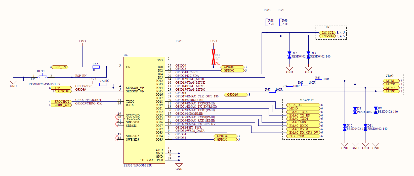
unfortnuately this is not possible anymore. As you can see from my schematic all pins are pretty much occupied. Also the physical board would need a lot of rework to do that. Only option is JTAG.
Have you checked EN and GPIO00? Are they both pulled high? What’s the matter with the crossed out pull-up resistor of GPIO00?
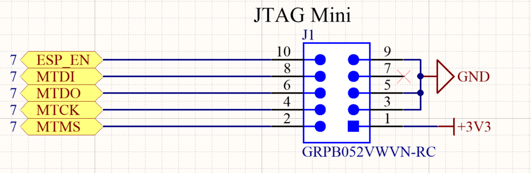
Which pins on the JTAG header are connected (except TDI, TCK, TMS and TDO)? And have you made sure the JTAG connector is not wired in a mirrored layout?
Are you sure the 100Ω resistors and ESD protection on the JTAG wires are no problem? Are they needed?
EDIT: Naming is a little bit confusing. It’s actually SWD pinning and connector, I have an adapter for j-link.
100Ohm and TVS diodes may not be necessary, but it does not hurt. I checked on another ESP32 dev board if adding the 100Ohm causes any problem and it does not.
In the meantime I did the following I skipped my boards PSU and powered the ESP from an external 3.3V but it did not change anything.
Is the default bootloader able to receive uploads via JTAG?
I don’t have an oscilloscope at the moment but I will try next week as i anyways need to order one. Any way to check if ESP32 is on with a multimeter?
I also tried disconnecting EN but it did not work.
Today I will try VisualGDB to check if it is software/GDB related.
Is my schematic correct, or is there anything i am missing?
I now measured with an oscilloscope. GPIO15 (TDO) is always high. In fact, ESP32 seems to be stuck in reset as all strapping pins are always in their default state. Any ideas?
I checked all pins, they look fine besides the freezing strapping pins. No noise or spikes.
I only powered the ESP32 portion of my board with external 3.3V.
I checked the scheamtic and footprints several times already. I haven’t found anything so far. In fact, I soldered some wires on a blank WROOM-32u module to “rebuild” parts of my board on a breadboard - it works…
Removing the ESP32 module would be really the last step, as I need to desolder it and there are several parts around it so it will not be easy and I want to avoid to damage the board.
For some reason, I suspect the enable/function on the ESP. It looks like it’s stuck in hardware reset.
Good news
It works now! I don’t know why but after one week of trial and error it works now…
I had to flash it first over serial and since then it works… This is very strange.
EDIT: As you can see in the schematic I forgot to put a decoupling capacitor between ESP 3.3V and GND pins. Although my power supply was stable, this missing capacitor caused the issue that ESP was constantly resetting. So if anyone has a similar issue: Put a decoupling cap close to the ESP32!