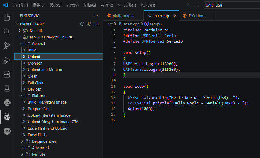
This board has 2 USB-C sockets, meant for upload/monitoring:
1 labeled UART1 (wich is shared with the UART2 plug, select by DIP switch)
1 labeled USB
Using the UART1 plug, everything works fine, but, I need that UART2 socket for communication.
Using the USB port, I have following issues:
PIO uploads through COM4, but for monitoring, I can only choose COM3.
Therefore, Serial moitor and ESP Decoder are not working.
I need to power cycle the board with BOOT pressed every time I want to upload and powercycle the board after every upload.
The reset button does not do the trick, only pulling the plug works, which will chew up the plug in no time…
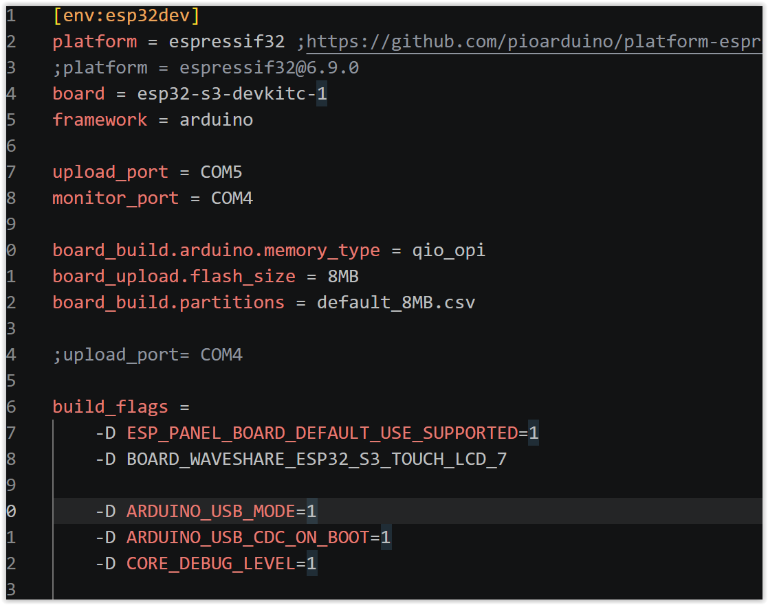
For using the USB port I added these to platformio.ini
-D ARDUINO_USB_MODE=1
-D ARDUINO_USB_CDC_ON_BOOT=1
-D CORE_DEBUG_LEVEL=1
So… it “kinda almost nearly works a little bit”, but does anyone know what I’m doing wrong here?
Check which COM port is the CDC serial port. After the sketch starts, open Device Manager. You should see a USB Serial (CDC) device. That is the port the Arduino Serial object uses. It may not be the same port used for uploading.
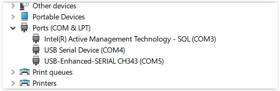
When I powercycle the board in BOOT mode, device manager shows 2 COM ports:
Intel(R) Active Management Technology - SOL (COM3)
USB Serial Device (COM4)
After uploading, it still shows the 2 ports, but the sketch doesn’t run.
If I powercycle it again, the sketch starts, and it shows only 1 port:
Intel(R) Active Management Technology - SOL (COM3)
It’s like the board is only visible to Windoze when it’s in BOOT mode… COM3 is also there when the board is unplugged… I do not really know what it’s representing…
The UART might appear under “Ports (COM & LPT)” in Device Manager. Please check there.
COM3 is for SOL (Serial On LAN), so it is not directly relevant.
Also, with your current environment settings, Serial refers to the native USB port. If you want to output to UART0, please try using Serial0.
(Example) Serial0.begin(115200); Serial.println(“Hello,World”);
Alternatively, please remove:
-D ARDUINO_USB_CDC_ON_BOOT=1
Doing so should allow you to load the program via UART, eliminating the need to operate the Boot switch.
Then, by using the following example, “Hello, World” should be output via the USB port:
(Example) USBSerial.begin(115200); USBSerial.println(“Hello,World”);
In device manager, both, COM3 and COM4 (whenever it’s there) are in the ports section. I guess that’s kinda where ports belong
No, I actually want to output to the USB port, as mentioned, if I connect via UART plug, everything works hunky dory. The problems arise when I try to connect to the USB socket.
Removing -D ARDUINO_USB_CDC_ON_BOOT=1seems to make no difference, same behaviour.
I cannot execute USBSeial.begin() → identifier “USBSerial” is undefined
Am I missing a library here?
The thread you linked is “a step further”… he is only having issues with the init of his serial communication being slow as I understand.
I don’t expect the core of the problem to be in the sketch, since windoze never sees the board (except it’s powercycled into BOOT mode)…
I would rather expect the issue in platformio.ini or in some windoze settings/drivers…
I apologize for the inadequacy of my previous proposal, which led to an error.
My response was based on the environment I had tested previously.
Although I do not have the exact same device, I do have an N16R8 S3 board,
so I will verify the matter again using that.
I conducted the following tests on Windows 11 using a board equipped with the ESP32-S3-N16R8.
Please pay attention to the differences between my setup and yours. Note that in my configuration, the UART port is COM19.
It worked successfully.
Thanks, unfortunately, the only reason for me to want to use the USB interface is to have the UART free for another purpose. If I use the UART socket, anyhow everything works just fine.
The main problem is:
When using the USB socket, Windows can only detect the board in bootloader mode.
If I get this solved, I think the other issues disappear.
I see threads about very similar problems on ESP32 S2, S3 and C3. Apparently only with PIO.
There is lots of questions, but I can’t seem to find any answer to it.
I start thinking I’ll just use UART for upload/monitoring and will communicate with the other ESP32 with ESPNOW or I2C…
The code I provided loads and connects to the PC in exactly the same way on both Windows 11 and Ubuntu 24.04.4 (though the port definitions differ). Therefore, I believe that if the program loads successfully, the device itself should function correctly.
Since Windows recognizes the USB connection in boot mode as COM4, there are no driver issues. The problem likely lies in the device initialization not being performed correctly.
I had assumed that simply swapping COM19 for COM5 (UART) and COM3 for COM4 (USB) would make it work; am I correct in understanding that this did not succeed?
If you haven’t given up on resolving this issue yet, could you please share your current platformio.ini and setup() code (specifically the version that fails to connect to the PC’s USB port)?
This community has many talented members who can offer suggestions from a variety of perspectives.
You are likely to receive even better answers than I could provide.
void setup()
{
    USBSerial.begin(115200);
    UARTSerial.begin(115200);

    Board *board = new Board();
    board->init();

    #if LVGL_PORT_AVOID_TEARING_MODE
    auto lcd = board->getLCD();
    // When avoid tearing function is enabled, the frame buffer number should be set in the board driver
    lcd->configFrameBufferNumber(LVGL_PORT_DISP_BUFFER_NUM);

#if ESP_PANEL_DRIVERS_BUS_ENABLE_RGB && CONFIG_IDF_TARGET_ESP32S3
    auto lcd_bus = lcd->getBus();
    /**
     * As the anti-tearing feature typically consumes more PSRAM bandwidth, for the ESP32-S3, we need to utilize the
     * "bounce buffer" functionality to enhance the RGB data bandwidth.
     * This feature will consume `bounce_buffer_size * bytes_per_pixel * 2` of SRAM memory.
     */
    if (lcd_bus->getBasicAttributes().type == ESP_PANEL_BUS_TYPE_RGB) {
        static_cast<BusRGB *>(lcd_bus)->configRGB_BounceBufferSize(lcd->getFrameWidth() * 10);
    }
#endif

#endif
    assert(board->begin());

    //Serial.println("Initializing LVGL");
    lvgl_port_init(board->getLCD(), board->getTouch());
    lvgl_port_lock(-1); //mutex
    lvgl_styles();
    lvgl_mainScreen();
    lv_scr_load(scrMain);
    lvgl_port_unlock();
}
Your last question, (the table), I cannot really follow..
I want:
No cable on the UART socket, as this will be used otherwise
Upload AND monitoring through the USB port
Board being recognized by windoze without being in boot mode
All of it works with your sketch, but not with mine, and I couldn’t figure why…
It seems you have put a lot of effort into this, so I would first like to say, “Great job.”
Since you confirmed that the sample code I provided works, you should be able to identify the problematic area by carefully comparing it with your own code.
There are many community members with far more knowledge in this field than I have, so I expect you will receive even more helpful advice soon.
That said, since we have come this far together, let me offer two additional suggestions.
1.platformio.ini
Your device is equipped with PSRAM (8MB), so
please select “ESP32-S3-DEVKITC-1-N8R8” as the board,
or try adding the following build option: -D BOARD_HAS_PSRAM=1
This is because LVGL requires a significant amount of RAM, yet the board JSON file for
“ESP32-S3-DEVKITC-1” does not include a PSRAM definition.
If the above does not resolve the issue, why not try the following?
2. setup()
Try pausing execution immediately after initializing the serial ports to see what happens.
Specifically, add the following code after USBSerial.begin(115200); and UARTSerial.begin(115200); : while(1) { USBSerial.println(“USBSerial”); UARTSerial.println(“UARTSerial”); delay(1000); }
This essentially reproduces the state of the sample code.
If you get output via both UART and USB—just like with the sample code—
then the problem likely lies somewhere in the subsequent code.
If you do not get the same output as the sample code,
it suggests there is an issue with your platformio.ini settings.
By gradually moving this while() loop further down through your code,
you should be able to pinpoint exactly where the problem is occurring.
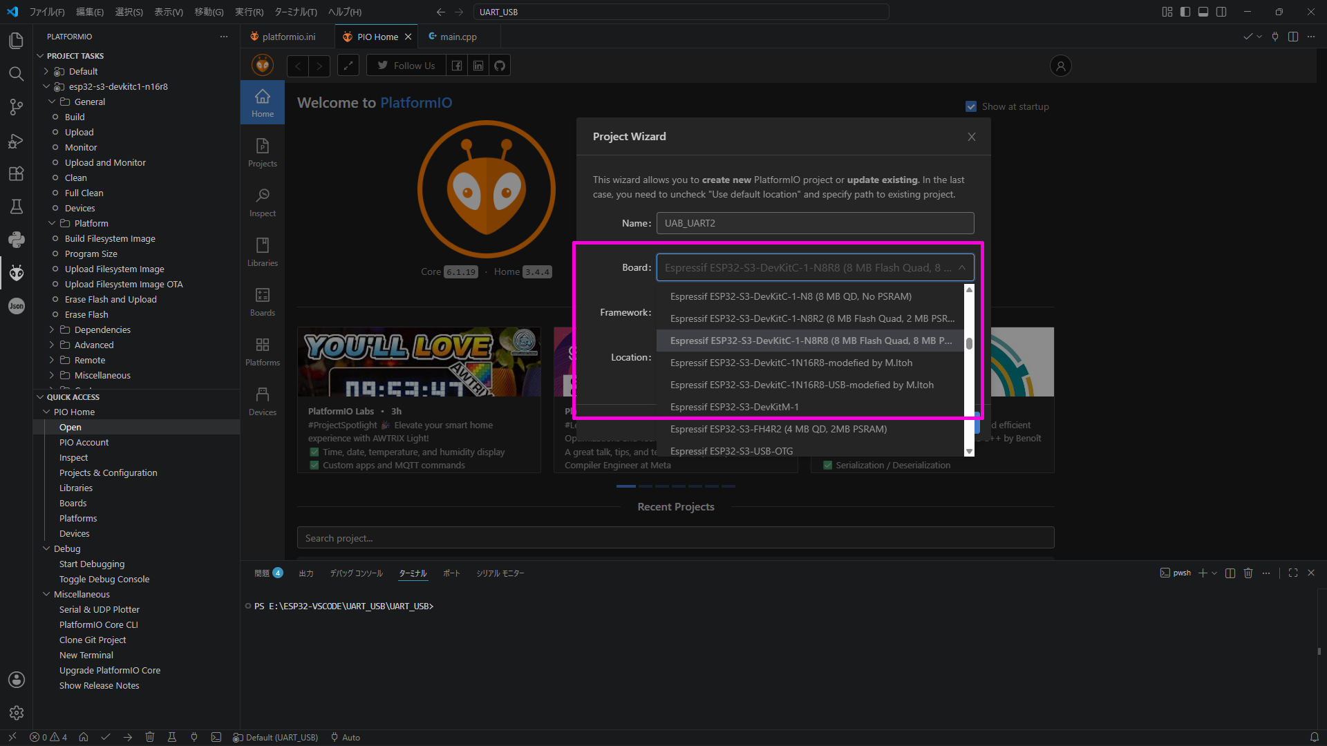
I am sorry for giving bad information. The platformio.ini setting must be as shown below:
board = esp32-s3-devkitc1-n8r8
If you specify the board this way, there is no need to include -D BOARD HAS PSRAM=1.
However, if you have a specific reason for needing to keep the board set as esp32-s3-devkitc-1, then you should use -D BOARD HAS PSRAM=1.
Alternatively—though it requires a bit more effort—you can create a new project from scratch and select the board from the drop-down list (please refer to the screenshot). This ensures the board is selected correctly.
Note, however, that with this method, you will need to manually copy over any work you have already completed in the current project.
I could kinda track down where this behaviour originates.
If I remove everthing LVGL, it’s still the same.
If then I remove in setup (and all subsequent references):
Board *board = new Board();
board->init();
Everything works.
But unfortunately this is needed for the LVGL port…
These 2 lines refer to esp_panel_board.hpp (part of ESP32_Display_Panel), and is somehow defining board and display. Unfortunately for me it’s “written in klingonian”. way above my paygrade…
So the culprit is ESP32_Display_Panel, respectively it’s configuration.
I’m glad to hear you’ve managed to make some progress.
However, unfortunately, I have absolutely no experience with this particular device, so I don’t think I can offer any insightful advice.
Please hang in there and keep at it.