Hi, @maxgerhardt. Thanks for answering.
The schematics are these: GitHub - LilyGO/TTGO-LORA32: ESP32-TTGO-T3 (v2.0)
AFAIK, the TTGO LoRa 32 has ESP32-Pico-D4, in case that helps.
I checked with a multimeter the IO0 (GPIO0), the next one to the 3.3v in the left row, and it the IO0 has 3.147v. (DC volts between that pin and GND). When I upload the program/bin it is the same all time (I measured until I saw the “Timed out”).
I can try what you suggest, but what I don’t understand is, why I could upload many programs before? Or have change the board internally and the GPIO0 now “emits” 3.3v and before was 0, allowing me to bootload programs? I understood that this board doesn’t need the BOOT button since it will manage it by itself (as it was doing previously).
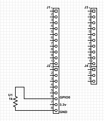
With this new info, do you recommend me to still connect the IO0 (which emits 3.3v) pin to the GND? better to connect them using a resistor (using the below diagram)? or better another option?
I only tried this until you say to me the next step (of the above questions):
- board connected
miniterm.py /dev/ttyUSB0 115200- nothing appears, but if I press RESET button in the board, I get a newline in the miniterm.
Also, another test. If I do the above without pressing RESET button, and from another terminal I try to upload the program (eg. arduino ide > upload), I get the same “Timed out” but in the miniterm terminal I get many empty newlines (like when pressing RESET button, but around 10-12).
Some more info about the V2:
There is no version label on the PCB.
Has on-board metal Wifi/Bluetooth antenna on bottom (in a better location than V1).
Uses ESP32-Pico-D4 (with integrated flash memory) instead of ESP32, uses a (shielded) SX1276 LoRa module, I-Pex connector located on the bottom, micro-USB connector is rotated 90 degrees, in addition has a microSD card slot on the bottom and an on/off switch for the battery next to the micro-USB connector. Switches the battery only so not possible to switch the board off when connected to USB for charging the battery.
User LED is connected to GPIO25 which is useless because that is already used for the display and all LEDs are on the bottom side. DIO1 and DIO2 have a separate pins and are not wired on the PCB to a GPIO port so must be manually wired. The LoRa modules are HPD13A and HPD14A from HPDTek.

Absolute MAX 12mA per pin, recommended 6mA.
GPIO 34-39 are input only.
Note that LoRa Reset is not connected to any GPIO,
but is hard-wired to the ESP32 Chip Enable (EN) pin.
I understand that you say this. If am wrong, please, correct me:
Edit: some traces, trying another program and trying another serial device port ttyUSB1 (connecting in the USB0 the arduino):
$ python /home/user/.arduino15/packages/esp32/tools/esptool_py/2.6.1/esptool.py --trace --chip esp32 --port /dev/ttyUSB1 --baud 115200 --before default_reset --after hard_reset write_flash -z --flash_mode dio --flash_freq 80m --flash_size detect 0xe000 /home/user/.arduino15/packages/esp32/hardware/esp32/1.0.4/tools/partitions/boot_app0.bin 0x1000 /home/user/.arduino15/packages/esp32/hardware/esp32/1.0.4/tools/sdk/bin/bootloader_dio_80m.bin 0x10000 /tmp/arduino_build_642061/GetChipID.ino.bin 0x8000 /tmp/arduino_build_642061/GetChipID.ino.partitions.bin
esptool.py v2.6
Serial port /dev/ttyUSB1
Connecting...TRACE +0.000 command op=0x08 data len=36 wait_response=1 timeout=0.100 data=
    0707122055555555 5555555555555555 | ... UUUUUUUUUUUU
    5555555555555555 5555555555555555 | UUUUUUUUUUUUUUUU
    55555555                          | UUUU
TRACE +0.000 Write 46 bytes:
    c000082400000000 0007071220555555 | ...$........ UUU
    5555555555555555 5555555555555555 | UUUUUUUUUUUUUUUU
    5555555555555555 5555555555c0     | UUUUUUUUUUUUU.
TRACE +0.091 Read 1 bytes: 0d
TRACE +0.000 Read invalid data: 0d
TRACE +0.000 Remaining data in serial buffer: 0a0d0a
.TRACE +0.050 command op=0x08 data len=36 wait_response=1 timeout=0.100 data=
    0707122055555555 5555555555555555 | ... UUUUUUUUUUUU
    5555555555555555 5555555555555555 | UUUUUUUUUUUUUUUU
    55555555                          | UUUU
TRACE +0.000 Write 46 bytes:
    c000082400000000 0007071220555555 | ...$........ UUU
    5555555555555555 5555555555555555 | UUUUUUUUUUUUUUUU
    5555555555555555 5555555555c0     | UUUUUUUUUUUUU.
TRACE +0.101 Timed out waiting for packet header
.TRACE +0.050 command op=0x08 data len=36 wait_response=1 timeout=0.100 data=
    0707122055555555 5555555555555555 | ... UUUUUUUUUUUU
    5555555555555555 5555555555555555 | UUUUUUUUUUUUUUUU
    55555555                          | UUUU
TRACE +0.000 Write 46 bytes:
    c000082400000000 0007071220555555 | ...$........ UUU
    5555555555555555 5555555555555555 | UUUUUUUUUUUUUUUU
    5555555555555555 5555555555c0     | UUUUUUUUUUUUU.
TRACE +0.100 Timed out waiting for packet header
.TRACE +1.812 command op=0x08 data len=36 wait_response=1 timeout=0.100 data=
    0707122055555555 5555555555555555 | ... UUUUUUUUUUUU
    5555555555555555 5555555555555555 | UUUUUUUUUUUUUUUU
    55555555                          | UUUU
TRACE +0.000 Write 46 bytes:
    c000082400000000 0007071220555555 | ...$........ UUU
    5555555555555555 5555555555555555 | UUUUUUUUUUUUUUUU
    5555555555555555 5555555555c0     | UUUUUUUUUUUUU.
TRACE +0.100 Timed out waiting for packet header
_TRACE +0.050 command op=0x08 data len=36 wait_response=1 timeout=0.100 data=
    0707122055555555 5555555555555555 | ... UUUUUUUUUUUU
    5555555555555555 5555555555555555 | UUUUUUUUUUUUUUUU
    55555555                          | UUUU
TRACE +0.000 Write 46 bytes:
    c000082400000000 0007071220555555 | ...$........ UUU
    5555555555555555 5555555555555555 | UUUUUUUUUUUUUUUU
    5555555555555555 5555555555c0     | UUUUUUUUUUUUU.
TRACE +0.101 Timed out waiting for packet header
_TRACE +0.050 command op=0x08 data len=36 wait_response=1 timeout=0.100 data=
    0707122055555555 5555555555555555 | ... UUUUUUUUUUUU
    5555555555555555 5555555555555555 | UUUUUUUUUUUUUUUU
    55555555                          | UUUU
TRACE +0.000 Write 46 bytes:
    c000082400000000 0007071220555555 | ...$........ UUU
    5555555555555555 5555555555555555 | UUUUUUUUUUUUUUUU
    5555555555555555 5555555555c0     | UUUUUUUUUUUUU.
TRACE +0.100 Timed out waiting for packet header
_TRACE +0.050 command op=0x08 data len=36 wait_response=1 timeout=0.100 data=
    0707122055555555 5555555555555555 | ... UUUUUUUUUUUU
    5555555555555555 5555555555555555 | UUUUUUUUUUUUUUUU
    55555555                          | UUUU
TRACE +0.000 Write 46 bytes:
    c000082400000000 0007071220555555 | ...$........ UUU
    5555555555555555 5555555555555555 | UUUUUUUUUUUUUUUU
    5555555555555555 5555555555c0     | UUUUUUUUUUUUU.
TRACE +0.100 Timed out waiting for packet header
_TRACE +0.211 command op=0x08 data len=36 wait_response=1 timeout=0.100 data=
    0707122055555555 5555555555555555 | ... UUUUUUUUUUUU
    5555555555555555 5555555555555555 | UUUUUUUUUUUUUUUU
    55555555                          | UUUU
TRACE +0.000 Write 46 bytes:
    c000082400000000 0007071220555555 | ...$........ UUU
    5555555555555555 5555555555555555 | UUUUUUUUUUUUUUUU
    5555555555555555 5555555555c0     | UUUUUUUUUUUUU.
TRACE +0.091 Read 1 bytes: 0d
TRACE +0.000 Read invalid data: 0d
TRACE +0.000 Remaining data in serial buffer: 0a0d0a
.TRACE +0.050 command op=0x08 data len=36 wait_response=1 timeout=0.100 data=
    0707122055555555 5555555555555555 | ... UUUUUUUUUUUU
    5555555555555555 5555555555555555 | UUUUUUUUUUUUUUUU
    55555555                          | UUUU
.... continue like this "loop" for 650 lines.