First, I have no idea why it stopped working. But since I have seen problems with this board more times before, I am not surprised… ![]()
This board got undetected and I was frustrated after some tests. Then, I directly bought another… that after some tests and trials for one day, the upload stopped working (check for the solution TTGO LoRa32 V2 Cannot upload - Timed out (tried many things) - #2 by maxgerhardt).
Now, I would like to see if the first board has any solution. I have to say that this board (and another one, previous to that one) got some problem like this in the past (1-2years ago) and a electrical engineer helped me: his diagnostic was that the diode was broken, so he directly replace it with another (SS14). I remember to ask why that, and he say something like “it does not matter which one, a diode is not so sensible”. But that did the trick and it got restored working. ![]()
I asked him and he just said that if the diode is working it should show a huge resistance in one direction. I did that, and I assumed it is, so it seems it is not broken. But due to the quarantine we cannot meet each other, so, I have to ask in this forum.
So, let’s go for it.
First, the board is TTGO LoRa32 V2.0
“Schematics” GitHub - LilyGO/TTGO-LORA32: ESP32-TTGO-T3
Has on-board metal Wifi/Bluetooth antenna on bottom (in a better location than V1).
Uses ESP32-Pico-D4 (with integrated flash memory) instead of ESP32, uses a (shielded) SX1276 LoRa module, I-Pex connector located on the bottom, micro-USB connector is rotated 90 degrees, in addition has a microSD card slot on the bottom and an on/off switch for the battery next to the micro-USB connector. Switches the battery only so not possible to switch the board off when connected to USB for charging the battery.
User LED is connected to GPIO25 which is useless because that is already used for the display and all LEDs are on the bottom side. DIO1 and DIO2 have a separate pins and are not wired on the PCB to a GPIO port so must be manually wired. The LoRa modules are HPD13A and HPD14A from HPDTek.
Absolute MAX 12mA per pin, recommended 6mA.
GPIO 34-39 are input only.
Note that LoRa Reset is not connected to any GPIO, but is hard-wired to the ESP32 Chip Enable (EN) pin.
I cannot upload multiple images, so I combine all at the end.
Now, pictures of a brand new board (working): first 2 captures.
There are more SMD components below the board/PCB, if you want I can do near pics.
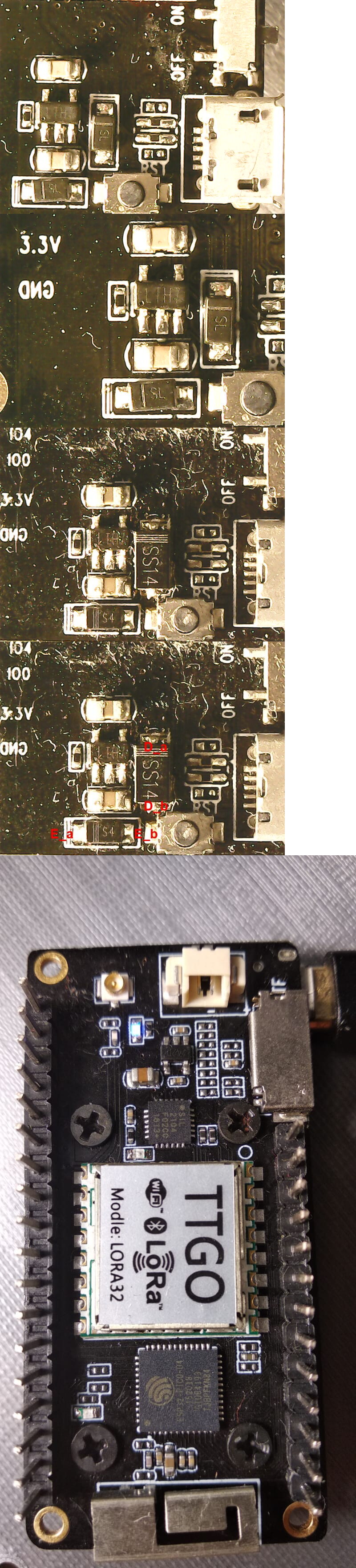
And the board that is undetected (next picture).
Now some measures using this marked pic (the same marks for both boards, although in this pic you see only the SS14 diode, not the stock diode) (fourth picture):
New board, all measures with multimeter between the X pin and the GND:
- 3v3: 3.2v
- IO0: 0.294v
- 5v: 4.2v
- D_a: 4.4v
- D_b: 4.8v
- E_a: oscillates between 4.1 and 4.5v
- E_b: oscillates between 4.1 and 4.6v
Undetected board:
- 3v3: 0.025v - 0.060v
- IO0: 0.025v - 0.060v
- 5v: 4.7v
- D_a: 4.7v
- D_b: 5v
- E_a: 0.002v
- E_b: 0.008v
Now, resistences with the boards disconnected:
New board:
- Multimeter in E_b (+) and E_a (-): 0.767 kOhm
- E_a (+) and E_b (-): oscillates between 0 and 0.25 kOhm
- D_a (+) and D_b (-): 490 kOhm (but continues increasing slowly every second ~ 1kOhm)
- D_b (+) and D_a (-): 0.8 kOhm
Undetected board:
- Multimeter in E_b (+) and E_a (-): 1.2 kOhm
- E_a (+) and E_b (-): fluctuates, but around 10 MOhm!
- D_a (+) and D_b (-): sometimes I see 0.5 MOhm, sometimes 50 MOhm or 0.L (out of range?)
- D_b (+) and D_a (-): sometimes 0.07 MOhm sometimes 2.88 kOhm
I hope I measured everything correctly. Do you recommend me any other test? Should I replace the SS14 again?
When I say that it is undetected I mean 2 things:
- When connected to the usb it is neither listed in
lsusb, nor listed in ports (arduino ide), nor devices list (platformio) - When power on, the device has only one led light (blue), but the display or other led lights are not working, as can be seen here (last pic):