Whilst trying to install and fit a SKR Turbo 1.4 Turbo Motherboard into 3D printer body…
I managed to break the SKR 1.4 Turbo Motherboard SD-CARD Reader!
(The card reader is not flush and protrudes from the board…it peeled the reader from the pcb!)I attempted to fix it without success! I have since removed it from the Motherboard (the original SD-Card Reader p.c.b pads are not intact… so connecting a new SD-Card Reader in place is not possible)
Have I bricked my brand new motherboard??!
Please can anyone suggest (If possible):
[1] a way that this could be rectified in respect to uploading/flashing the marlin 2 firmware to the SKR 1.4 Turbo without the original SD-Card Reader Module?
I am under the impression I may be able to use a programmer of some description to upload the firmware?
[2] Installation of a new SD-Card Reader that could be used instead of the built in default SD-Card Reader?
I think I would be required to first modify marlin and then flash the motherboard firmware? (See question [1]) Then prehaps be able to connect another SD-Card reader to the motherboard via SPI or alternative e.g wires to the respective pins on the reverse of the**board?
Could somebody kindly point me in the right direction?
I would appreciate some guidance if this indeed possible?
Is just the socket connection defective or is the firmware or bootloader on the board dead as well? If it’s just a socket connection, the printer should still power up and display something, right?
PlatformIO (or rather, the custom third-party platform code) is able to upload a firmware directly via some upload methods: See GitHub - maxgerhardt/pio-nxp-lpc1769-arduino-test: Simple project for testing Arduino support on the NXP LPC1769 chip using a custom platform.. However, if there is a bootloader involved, things might be different. Uploading a firmware this way to the wrong address will override the bootloader, and you really don’t want that. So the safest route would be to let PlatformIO generate the Marlin build and then take the compiled .bin file and let the SD card bootloader handle the rest. If you have no restraint in experimenting with direct uploading (and fixing some upload addresses if they’re wrong), you can try it… You should work on obtaining a full memory dump of the current flash though first, as that will be your only means of recovering.
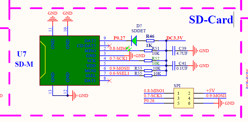
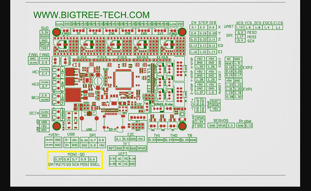
As you can see in the schematics, the SPI pins are simply duplicated on the SPI header, together with a +5V supply.
If none of the traces are physically broken (the connections on the SPI header still go through to the MCU), that should be the easiest method of fixing.
That is indeed a caveat I’ve just noticed too. P0.27 is used on the on-board SD card connector as the SDDET signal, SD detection. If that signal is GND, it tells the MCU that a SD card is inserted. See Adafruit guide: Introduction | Micro SD Card Breakout Board Tutorial | Adafruit Learning System. The pin may also be just ignored by the bootloader.
Seems to me that the purpose of the SPI connector is to connect other SPI devices, and P0.26 is simply usable as a chip-select signal for other devices.
So I actually have to correct myself: Some modifications need to be done.
P0.27 has to go to the “CD” pin (“card detect”) of the adapter; e.g. via a soldered wire from the correct side of D7 (facing P0.27) to CD
P0.6-SSEL1 is the slave-select / chip select of the original SD card and is not available on the SD card header. Again that has to connected, via a soldered via, to the SD adapter as the chip select pin, e.g. from the correct side of R55, facing the 0.6-SSEL1 pin.
Rest of the SPI bus can be connected from the header (MISO, MOSI, SCLK)
Of course, if you have a soldering iron to create connections to a new SD card adapter, you might as well just try and resolder the SD reader module, depending on how exactly it’s broken. Did the solder just break foff cleanly? Or did the entire pad and trace lift off, too, right requires additional patchup?
again i really appreciate the effort.
sorry for my ignorance (this is hurting my tiny brain!)
so to clarify
would rewiring the adafruit to the spi with the mods you mentioned allow me to write the firmware using pio? or would i need to copy it to the sd card.
would the firmware require any modifications to use the SPI
or do i need to use the github dist you have provided?
when i peeled the sd-card module it only broke the soldering on about 5 pins
i was able to repair this with a soldering iron
the board when plugged into windows opened the sd-card and i was able to upload the firmware!
i was very happy! … however i made a critical error afterwards!
as the card required force to insert and eject the media… i superglued the edges in an attempt to prevent the sd module from moving and damaging the re-soldered pins.
thinking all would be good. i allowed the glue to dry.
when trying to insert the sd card again (i wish i would have glued it in too!!!) the card would not latch into the module!
so in short: after repair/saving it! i broke it again!!
so i had no choice to remove the module (which required breaking it open- therefore rendering it unusable!
in desperation : i began to solder some wires to the pins. i used my soldering iron on the lowest heat setting but i unfortunately removed the copper pad on one of the pins DAT1 as per the schematic you provided)!
By rewiring you will be able to use the external SD card module instead of the on-board SD card module. The new firmware still has to be put on the SD card and inserted into the new SD card module. You’re basically just strapping a working SD card module on top of the broken one with that method.
Since method above would hi-jack the existing SPI lines (most importantly same slave-select and SD card detect), no modifications to the firmware need to be done – it’s a hardware fix only.
you are wonderful for taking more time to spoon feed me
thank you so very much
i must admit after the initial despair of breaking the motherboard
and then performing the first repair i was very happy only to be shortly returned to sadness
thank you for providing the information!
i feel i might just be able to fix this without having to bin and purchase a new skr1.4 (although it might take me some time to comprehend what i need to do!)
i am currently working on a schematic so i can see what wires go where etc
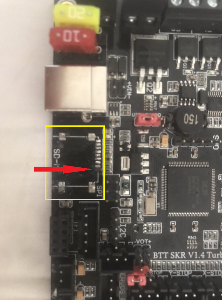
No problem. What would help though is a high-resolution, clear picture of micro SD port. There are no layout files available for this board, so I just have to work with the schematic and some 3D renderings. A close-up up shot of that row of components (resistors, capacitors, that one diode) would be great. Basically a clearer picture of the yellow rectangle (including more to the right though).
I’m getting a “you need access” message from the google drive there. Can you switch it to “Accessible by everyone with a link” in your google drive? Right now it’s by invitation only.