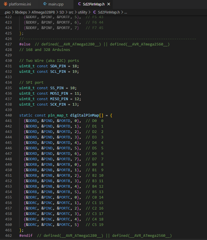
This is the Sd2PinMap.h code
#if defined(__arm__) // Arduino Due Board follows

#ifndef Sd2PinMap_h
  #define Sd2PinMap_h

  #include <Arduino.h>

  uint8_t const SS_PIN = SS;
  uint8_t const MOSI_PIN = MOSI;
  uint8_t const MISO_PIN = MISO;
  uint8_t const SCK_PIN = SCK;

#endif // Sd2PinMap_h

#elif defined(__AVR_ATmega4809__) // Arduino UNO WiFI Rev2 follows

#ifndef Sd2PinMap_h
  #define Sd2PinMap_h

  #include <Arduino.h>

  uint8_t const SS_PIN = SS;
  uint8_t const MOSI_PIN = MOSI;
  uint8_t const MISO_PIN = MISO;
  uint8_t const SCK_PIN = SCK;

#endif // Sd2PinMap_h

#elif defined(__AVR__) // Other AVR based Boards follows

// Warning this file was generated by a program.
#ifndef Sd2PinMap_h
#define Sd2PinMap_h
#include <avr/io.h>

//------------------------------------------------------------------------------
/** struct for mapping digital pins */
struct pin_map_t {
  volatile uint8_t* ddr;
  volatile uint8_t* pin;
  volatile uint8_t* port;
  uint8_t bit;
};
//------------------------------------------------------------------------------
#if defined(__AVR_ATmega1280__) || defined(__AVR_ATmega2560__)
// Mega

// Two Wire (aka I2C) ports
uint8_t const SDA_PIN = 20;
uint8_t const SCL_PIN = 21;

// SPI port
uint8_t const SS_PIN = 53;
uint8_t const MOSI_PIN = 51;
uint8_t const MISO_PIN = 50;
uint8_t const SCK_PIN = 52;

static const pin_map_t digitalPinMap[] = {
  {&DDRE, &PINE, &PORTE, 0},  // E0  0
  {&DDRE, &PINE, &PORTE, 1},  // E1  1
  {&DDRE, &PINE, &PORTE, 4},  // E4  2
  {&DDRE, &PINE, &PORTE, 5},  // E5  3
  {&DDRG, &PING, &PORTG, 5},  // G5  4
  {&DDRE, &PINE, &PORTE, 3},  // E3  5
  {&DDRH, &PINH, &PORTH, 3},  // H3  6
  {&DDRH, &PINH, &PORTH, 4},  // H4  7
  {&DDRH, &PINH, &PORTH, 5},  // H5  8
  {&DDRH, &PINH, &PORTH, 6},  // H6  9
  {&DDRB, &PINB, &PORTB, 4},  // B4 10
  {&DDRB, &PINB, &PORTB, 5},  // B5 11
  {&DDRB, &PINB, &PORTB, 6},  // B6 12
  {&DDRB, &PINB, &PORTB, 7},  // B7 13
  {&DDRJ, &PINJ, &PORTJ, 1},  // J1 14
  {&DDRJ, &PINJ, &PORTJ, 0},  // J0 15
  {&DDRH, &PINH, &PORTH, 1},  // H1 16
  {&DDRH, &PINH, &PORTH, 0},  // H0 17
  {&DDRD, &PIND, &PORTD, 3},  // D3 18
  {&DDRD, &PIND, &PORTD, 2},  // D2 19
  {&DDRD, &PIND, &PORTD, 1},  // D1 20
  {&DDRD, &PIND, &PORTD, 0},  // D0 21
  {&DDRA, &PINA, &PORTA, 0},  // A0 22
  {&DDRA, &PINA, &PORTA, 1},  // A1 23
  {&DDRA, &PINA, &PORTA, 2},  // A2 24
  {&DDRA, &PINA, &PORTA, 3},  // A3 25
  {&DDRA, &PINA, &PORTA, 4},  // A4 26
  {&DDRA, &PINA, &PORTA, 5},  // A5 27
  {&DDRA, &PINA, &PORTA, 6},  // A6 28
  {&DDRA, &PINA, &PORTA, 7},  // A7 29
  {&DDRC, &PINC, &PORTC, 7},  // C7 30
  {&DDRC, &PINC, &PORTC, 6},  // C6 31
  {&DDRC, &PINC, &PORTC, 5},  // C5 32
  {&DDRC, &PINC, &PORTC, 4},  // C4 33
  {&DDRC, &PINC, &PORTC, 3},  // C3 34
  {&DDRC, &PINC, &PORTC, 2},  // C2 35
  {&DDRC, &PINC, &PORTC, 1},  // C1 36
  {&DDRC, &PINC, &PORTC, 0},  // C0 37
  {&DDRD, &PIND, &PORTD, 7},  // D7 38
  {&DDRG, &PING, &PORTG, 2},  // G2 39
  {&DDRG, &PING, &PORTG, 1},  // G1 40
  {&DDRG, &PING, &PORTG, 0},  // G0 41
  {&DDRL, &PINL, &PORTL, 7},  // L7 42
  {&DDRL, &PINL, &PORTL, 6},  // L6 43
  {&DDRL, &PINL, &PORTL, 5},  // L5 44
  {&DDRL, &PINL, &PORTL, 4},  // L4 45
  {&DDRL, &PINL, &PORTL, 3},  // L3 46
  {&DDRL, &PINL, &PORTL, 2},  // L2 47
  {&DDRL, &PINL, &PORTL, 1},  // L1 48
  {&DDRL, &PINL, &PORTL, 0},  // L0 49
  {&DDRB, &PINB, &PORTB, 3},  // B3 50
  {&DDRB, &PINB, &PORTB, 2},  // B2 51
  {&DDRB, &PINB, &PORTB, 1},  // B1 52
  {&DDRB, &PINB, &PORTB, 0},  // B0 53
  {&DDRF, &PINF, &PORTF, 0},  // F0 54
  {&DDRF, &PINF, &PORTF, 1},  // F1 55
  {&DDRF, &PINF, &PORTF, 2},  // F2 56
  {&DDRF, &PINF, &PORTF, 3},  // F3 57
  {&DDRF, &PINF, &PORTF, 4},  // F4 58
  {&DDRF, &PINF, &PORTF, 5},  // F5 59
  {&DDRF, &PINF, &PORTF, 6},  // F6 60
  {&DDRF, &PINF, &PORTF, 7},  // F7 61
  {&DDRK, &PINK, &PORTK, 0},  // K0 62
  {&DDRK, &PINK, &PORTK, 1},  // K1 63
  {&DDRK, &PINK, &PORTK, 2},  // K2 64
  {&DDRK, &PINK, &PORTK, 3},  // K3 65
  {&DDRK, &PINK, &PORTK, 4},  // K4 66
  {&DDRK, &PINK, &PORTK, 5},  // K5 67
  {&DDRK, &PINK, &PORTK, 6},  // K6 68
  {&DDRK, &PINK, &PORTK, 7}   // K7 69
};
//------------------------------------------------------------------------------
#elif (defined(__AVR_ATmega644P__) || defined(__AVR_ATmega1284P__)) && defined(CORE_MICRODUINO)
// Microduino Core+

// Two Wire (aka I2C) ports
uint8_t const SDA_PIN = 20;
uint8_t const SCL_PIN = 21;

// SPI port
uint8_t const SS_PIN = 10;
uint8_t const MOSI_PIN = 11;
uint8_t const MISO_PIN = 12;
uint8_t const SCK_PIN = 13;

static const pin_map_t digitalPinMap[] = {
  {&DDRD, &PIND, &PORTD, 0},  // D0 PD0
  {&DDRD, &PIND, &PORTD, 1},  // D1 PD1
  {&DDRD, &PIND, &PORTD, 2},  // D2 PD2
  {&DDRD, &PIND, &PORTD, 3},  // D3 PD3
  {&DDRB, &PINB, &PORTB, 0},  // D4 PB0
  {&DDRB, &PINB, &PORTB, 1},  // D5 PB1
  {&DDRB, &PINB, &PORTB, 2},  // D6 PB2
  {&DDRB, &PINB, &PORTB, 3},  // D7 PB3
  {&DDRD, &PIND, &PORTD, 6},  // D8 PD6
  {&DDRD, &PIND, &PORTD, 5},  // D9 PD5
  {&DDRB, &PINB, &PORTB, 4},  // D10 PB4
  {&DDRB, &PINB, &PORTB, 5},  // D11 PB5
  {&DDRB, &PINB, &PORTB, 6},  // D12 PB6
  {&DDRB, &PINB, &PORTB, 7},  // D13 PB7
  {&DDRC, &PINC, &PORTC, 7},  // D14 PC7
  {&DDRC, &PINC, &PORTC, 6},  // D15 PC6
  {&DDRC, &PINC, &PORTC, 5},  // D16 PC5
  {&DDRC, &PINC, &PORTC, 4},  // D17 PC4
  {&DDRC, &PINC, &PORTC, 3},  // D18 PC3
  {&DDRC, &PINC, &PORTC, 2},  // D19 PC2
  {&DDRC, &PINC, &PORTC, 1},  // D20 PC1
  {&DDRC, &PINC, &PORTC, 0},  // D21 PC0
  {&DDRD, &PIND, &PORTD, 4},  // D22 PD4
  {&DDRD, &PIND, &PORTD, 7},  // D23 PD7
  {&DDRA, &PINA, &PORTA, 7},  // D24 PA7
  {&DDRA, &PINA, &PORTA, 6},  // D25 PA6
  {&DDRA, &PINA, &PORTA, 5},  // D26 PA5
  {&DDRA, &PINA, &PORTA, 4},  // D27 PA4
  {&DDRA, &PINA, &PORTA, 3},  // D28 PA3
  {&DDRA, &PINA, &PORTA, 2},  // D29 PA2
  {&DDRA, &PINA, &PORTA, 1},  // D30 PA1
  {&DDRA, &PINA, &PORTA, 0}   // D31 PA0
};
//------------------------------------------------------------------------------
#elif defined(__AVR_ATmega128RFA1__) && defined(CORE_MICRODUINO)
// Microduino Core RF

// Two Wire (aka I2C) ports
uint8_t const SDA_PIN = 18;
uint8_t const SCL_PIN = 19;

// SPI port
uint8_t const SS_PIN = 10;
uint8_t const MOSI_PIN = 11;
uint8_t const MISO_PIN = 12;
uint8_t const SCK_PIN = 13;

static const pin_map_t digitalPinMap[] = {
  {&DDRD, &PINE, &PORTE, 0},  // D0 PE0
  {&DDRD, &PINE, &PORTE, 1},  // D1 PE1
  {&DDRD, &PIND, &PORTD, 2},  // D2 PD2
  {&DDRD, &PIND, &PORTD, 3},  // D3 PD3
  {&DDRB, &PINE, &PORTE, 3},  // D4 PE3
  {&DDRB, &PINE, &PORTE, 4},  // D5 PE4
  {&DDRB, &PINE, &PORTE, 5},  // D6 PE5
  {&DDRB, &PINB, &PORTB, 7},  // D7 PB7
  {&DDRD, &PINB, &PORTB, 6},  // D8 PB6
  {&DDRD, &PINB, &PORTB, 5},  // D9 PB5
  {&DDRB, &PINB, &PORTB, 4},  // D10 PB4
  {&DDRB, &PINB, &PORTB, 2},  // D11 PB2
  {&DDRB, &PINB, &PORTB, 3},  // D12 PB3
  {&DDRB, &PINB, &PORTB, 1},  // D13 PB1
  {&DDRF, &PINF, &PORTF, 7},  // D14 PF7
  {&DDRF, &PINF, &PORTF, 6},  // D15 PF6
  {&DDRF, &PINF, &PORTF, 5},  // D16 PF5
  {&DDRF, &PINF, &PORTF, 4},  // D17 PF4
  {&DDRD, &PIND, &PORTD, 1},  // D18 PD1
  {&DDRD, &PIND, &PORTD, 0},  // D19 PD0
  {&DDRF, &PINF, &PORTF, 3},  // D20 PF3
  {&DDRF, &PINF, &PORTF, 2},  // D21 PF2
};
//------------------------------------------------------------------------------
#elif defined(__AVR_ATmega32U4__) && defined(CORE_MICRODUINO)
// Microduino Core USB

// Two Wire (aka I2C) ports
uint8_t const SDA_PIN = 18;
uint8_t const SCL_PIN = 19;

// SPI port
uint8_t const SS_PIN = 10;
uint8_t const MOSI_PIN = 11;
uint8_t const MISO_PIN = 12;
uint8_t const SCK_PIN = 13;

static const pin_map_t digitalPinMap[] = {
  {&DDRD, &PIND, &PORTD, 2},  // D0 - PD2
  {&DDRD, &PIND, &PORTD, 3},  // D1 - PD3
  {&DDRE, &PINE, &PORTE, 6},  // D2 - PE6
  {&DDRD, &PIND, &PORTD, 6},  // D3 - PD6
  {&DDRD, &PIND, &PORTD, 7},  // D4 - PD7
  {&DDRC, &PINC, &PORTC, 6},  // D5 - PC6
  {&DDRC, &PINC, &PORTC, 7},  // D6 - PC7
  {&DDRE, &PINE, &PORTE, 7},  // D7 - PE7
  {&DDRB, &PINB, &PORTB, 6},  // D8 - PB6
  {&DDRB, &PINB, &PORTB, 5},  // D9 - PB5
  {&DDRB, &PINB, &PORTB, 0},  // D10 - PB0
  {&DDRB, &PINB, &PORTB, 2},  // D11 - MOSI - PB2
  {&DDRB, &PINB, &PORTB, 3},  // D12 -MISO -  PB3
  {&DDRB, &PINB, &PORTB, 1},  // D13 -SCK -  PB1
  {&DDRF, &PINF, &PORTF, 7},  // D14 - A0 - PF7
  {&DDRF, &PINF, &PORTF, 6},  // D15 - A1 - PF6
  {&DDRF, &PINF, &PORTF, 5},  // D16 - A2 - PF5
  {&DDRF, &PINF, &PORTF, 4},  // D17 - A3 - PF4
  {&DDRD, &PIND, &PORTD, 1},  // D18 - PD1
  {&DDRD, &PIND, &PORTD, 0},  // D19 - PD0
  {&DDRF, &PINF, &PORTF, 1},  // D20 - A6 - PF1
  {&DDRF, &PINF, &PORTF, 0},  // D21 - A7 - PF0
};
//------------------------------------------------------------------------------
#elif defined(__AVR_ATmega644P__) || defined(__AVR_ATmega644__)
// Sanguino

// Two Wire (aka I2C) ports
uint8_t const SDA_PIN = 17;
uint8_t const SCL_PIN = 18;

// SPI port
uint8_t const SS_PIN = 4;
uint8_t const MOSI_PIN = 5;
uint8_t const MISO_PIN = 6;
uint8_t const SCK_PIN = 7;

static const pin_map_t digitalPinMap[] = {
  {&DDRB, &PINB, &PORTB, 0},  // B0  0
  {&DDRB, &PINB, &PORTB, 1},  // B1  1
  {&DDRB, &PINB, &PORTB, 2},  // B2  2
  {&DDRB, &PINB, &PORTB, 3},  // B3  3
  {&DDRB, &PINB, &PORTB, 4},  // B4  4
  {&DDRB, &PINB, &PORTB, 5},  // B5  5
  {&DDRB, &PINB, &PORTB, 6},  // B6  6
  {&DDRB, &PINB, &PORTB, 7},  // B7  7
  {&DDRD, &PIND, &PORTD, 0},  // D0  8
  {&DDRD, &PIND, &PORTD, 1},  // D1  9
  {&DDRD, &PIND, &PORTD, 2},  // D2 10
  {&DDRD, &PIND, &PORTD, 3},  // D3 11
  {&DDRD, &PIND, &PORTD, 4},  // D4 12
  {&DDRD, &PIND, &PORTD, 5},  // D5 13
  {&DDRD, &PIND, &PORTD, 6},  // D6 14
  {&DDRD, &PIND, &PORTD, 7},  // D7 15
  {&DDRC, &PINC, &PORTC, 0},  // C0 16
  {&DDRC, &PINC, &PORTC, 1},  // C1 17
  {&DDRC, &PINC, &PORTC, 2},  // C2 18
  {&DDRC, &PINC, &PORTC, 3},  // C3 19
  {&DDRC, &PINC, &PORTC, 4},  // C4 20
  {&DDRC, &PINC, &PORTC, 5},  // C5 21
  {&DDRC, &PINC, &PORTC, 6},  // C6 22
  {&DDRC, &PINC, &PORTC, 7},  // C7 23
  {&DDRA, &PINA, &PORTA, 7},  // A7 24
  {&DDRA, &PINA, &PORTA, 6},  // A6 25
  {&DDRA, &PINA, &PORTA, 5},  // A5 26
  {&DDRA, &PINA, &PORTA, 4},  // A4 27
  {&DDRA, &PINA, &PORTA, 3},  // A3 28
  {&DDRA, &PINA, &PORTA, 2},  // A2 29
  {&DDRA, &PINA, &PORTA, 1},  // A1 30
  {&DDRA, &PINA, &PORTA, 0}   // A0 31
};
//------------------------------------------------------------------------------
#elif defined(__AVR_ATmega32U4__)
// Leonardo

// Two Wire (aka I2C) ports
uint8_t const SDA_PIN = 2;
uint8_t const SCL_PIN = 3;

// SPI port
uint8_t const SS_PIN = 17;
uint8_t const MOSI_PIN = 16;
uint8_t const MISO_PIN = 14;
uint8_t const SCK_PIN = 15;

static const pin_map_t digitalPinMap[] = {
  {&DDRD, &PIND, &PORTD, 2},  // D2  0
  {&DDRD, &PIND, &PORTD, 3},  // D3  1
  {&DDRD, &PIND, &PORTD, 1},  // D1  2
  {&DDRD, &PIND, &PORTD, 0},  // D0  3
  {&DDRD, &PIND, &PORTD, 4},  // D4  4
  {&DDRC, &PINC, &PORTC, 6},  // C6  5
  {&DDRD, &PIND, &PORTD, 7},  // D7  6
  {&DDRE, &PINE, &PORTE, 6},  // E6  7
  {&DDRB, &PINB, &PORTB, 4},  // B4  8
  {&DDRB, &PINB, &PORTB, 5},  // B5  9
  {&DDRB, &PINB, &PORTB, 6},  // B6 10
  {&DDRB, &PINB, &PORTB, 7},  // B7 11
  {&DDRD, &PIND, &PORTD, 6},  // D6 12
  {&DDRC, &PINC, &PORTC, 7},  // C7 13
  {&DDRB, &PINB, &PORTB, 3},  // B3 14
  {&DDRB, &PINB, &PORTB, 1},  // B1 15
  {&DDRB, &PINB, &PORTB, 2},  // B2 16
  {&DDRB, &PINB, &PORTB, 0},  // B0 17
  {&DDRF, &PINF, &PORTF, 7},  // F7 18
  {&DDRF, &PINF, &PORTF, 6},  // F6 19
  {&DDRF, &PINF, &PORTF, 5},  // F5 20
  {&DDRF, &PINF, &PORTF, 4},  // F4 21
  {&DDRF, &PINF, &PORTF, 1},  // F1 22
  {&DDRF, &PINF, &PORTF, 0},  // F0 23
};
//------------------------------------------------------------------------------
#elif defined(__AVR_AT90USB646__) || defined(__AVR_AT90USB1286__)
// Teensy++ 1.0 & 2.0

// Two Wire (aka I2C) ports
uint8_t const SDA_PIN = 1;
uint8_t const SCL_PIN = 0;

// SPI port
uint8_t const SS_PIN = 20;
uint8_t const MOSI_PIN = 22;
uint8_t const MISO_PIN = 23;
uint8_t const SCK_PIN = 21;

static const pin_map_t digitalPinMap[] = {
  {&DDRD, &PIND, &PORTD, 0},  // D0  0
  {&DDRD, &PIND, &PORTD, 1},  // D1  1
  {&DDRD, &PIND, &PORTD, 2},  // D2  2
  {&DDRD, &PIND, &PORTD, 3},  // D3  3
  {&DDRD, &PIND, &PORTD, 4},  // D4  4
  {&DDRD, &PIND, &PORTD, 5},  // D5  5
  {&DDRD, &PIND, &PORTD, 6},  // D6  6
  {&DDRD, &PIND, &PORTD, 7},  // D7  7
  {&DDRE, &PINE, &PORTE, 0},  // E0  8
  {&DDRE, &PINE, &PORTE, 1},  // E1  9
  {&DDRC, &PINC, &PORTC, 0},  // C0 10
  {&DDRC, &PINC, &PORTC, 1},  // C1 11
  {&DDRC, &PINC, &PORTC, 2},  // C2 12
  {&DDRC, &PINC, &PORTC, 3},  // C3 13
  {&DDRC, &PINC, &PORTC, 4},  // C4 14
  {&DDRC, &PINC, &PORTC, 5},  // C5 15
  {&DDRC, &PINC, &PORTC, 6},  // C6 16
  {&DDRC, &PINC, &PORTC, 7},  // C7 17
  {&DDRE, &PINE, &PORTE, 6},  // E6 18
  {&DDRE, &PINE, &PORTE, 7},  // E7 19
  {&DDRB, &PINB, &PORTB, 0},  // B0 20
  {&DDRB, &PINB, &PORTB, 1},  // B1 21
  {&DDRB, &PINB, &PORTB, 2},  // B2 22
  {&DDRB, &PINB, &PORTB, 3},  // B3 23
  {&DDRB, &PINB, &PORTB, 4},  // B4 24
  {&DDRB, &PINB, &PORTB, 5},  // B5 25
  {&DDRB, &PINB, &PORTB, 6},  // B6 26
  {&DDRB, &PINB, &PORTB, 7},  // B7 27
  {&DDRA, &PINA, &PORTA, 0},  // A0 28
  {&DDRA, &PINA, &PORTA, 1},  // A1 29
  {&DDRA, &PINA, &PORTA, 2},  // A2 30
  {&DDRA, &PINA, &PORTA, 3},  // A3 31
  {&DDRA, &PINA, &PORTA, 4},  // A4 32
  {&DDRA, &PINA, &PORTA, 5},  // A5 33
  {&DDRA, &PINA, &PORTA, 6},  // A6 34
  {&DDRA, &PINA, &PORTA, 7},  // A7 35
  {&DDRE, &PINE, &PORTE, 4},  // E4 36
  {&DDRE, &PINE, &PORTE, 5},  // E5 37
  {&DDRF, &PINF, &PORTF, 0},  // F0 38
  {&DDRF, &PINF, &PORTF, 1},  // F1 39
  {&DDRF, &PINF, &PORTF, 2},  // F2 40
  {&DDRF, &PINF, &PORTF, 3},  // F3 41
  {&DDRF, &PINF, &PORTF, 4},  // F4 42
  {&DDRF, &PINF, &PORTF, 5},  // F5 43
  {&DDRF, &PINF, &PORTF, 6},  // F6 44
  {&DDRF, &PINF, &PORTF, 7}   // F7 45
};
//------------------------------------------------------------------------------
#else  // defined(__AVR_ATmega1280__) || defined(__AVR_ATmega2560__)
// 168 and 328 Arduinos

// Two Wire (aka I2C) ports
uint8_t const SDA_PIN = 18;
uint8_t const SCL_PIN = 19;

// SPI port
uint8_t const SS_PIN = 10;
uint8_t const MOSI_PIN = 11;
uint8_t const MISO_PIN = 12;
uint8_t const SCK_PIN = 13;

static const pin_map_t digitalPinMap[] = {
  {&DDRD, &PIND, &PORTD, 0},  // D0  0
  {&DDRD, &PIND, &PORTD, 1},  // D1  1
  {&DDRD, &PIND, &PORTD, 2},  // D2  2
  {&DDRD, &PIND, &PORTD, 3},  // D3  3
  {&DDRD, &PIND, &PORTD, 4},  // D4  4
  {&DDRD, &PIND, &PORTD, 5},  // D5  5
  {&DDRD, &PIND, &PORTD, 6},  // D6  6
  {&DDRD, &PIND, &PORTD, 7},  // D7  7
  {&DDRB, &PINB, &PORTB, 0},  // B0  8
  {&DDRB, &PINB, &PORTB, 1},  // B1  9
  {&DDRB, &PINB, &PORTB, 2},  // B2 10
  {&DDRB, &PINB, &PORTB, 3},  // B3 11
  {&DDRB, &PINB, &PORTB, 4},  // B4 12
  {&DDRB, &PINB, &PORTB, 5},  // B5 13
  {&DDRC, &PINC, &PORTC, 0},  // C0 14
  {&DDRC, &PINC, &PORTC, 1},  // C1 15
  {&DDRC, &PINC, &PORTC, 2},  // C2 16
  {&DDRC, &PINC, &PORTC, 3},  // C3 17
  {&DDRC, &PINC, &PORTC, 4},  // C4 18
  {&DDRC, &PINC, &PORTC, 5}   // C5 19
};
#endif  // defined(__AVR_ATmega1280__) || defined(__AVR_ATmega2560__)
//------------------------------------------------------------------------------
static const uint8_t digitalPinCount = sizeof(digitalPinMap) / sizeof(pin_map_t);

uint8_t badPinNumber(void)
__attribute__((error("Pin number is too large or not a constant")));

static inline __attribute__((always_inline))
uint8_t getPinMode(uint8_t pin) {
  if (__builtin_constant_p(pin) && pin < digitalPinCount) {
    return (*digitalPinMap[pin].ddr >> digitalPinMap[pin].bit) & 1;
  } else {
    return badPinNumber();
  }
}
static inline __attribute__((always_inline))
void setPinMode(uint8_t pin, uint8_t mode) {
  if (__builtin_constant_p(pin) && pin < digitalPinCount) {
    if (mode) {
      *digitalPinMap[pin].ddr |= 1 << digitalPinMap[pin].bit;
    } else {
      *digitalPinMap[pin].ddr &= ~(1 << digitalPinMap[pin].bit);
    }
  } else {
    badPinNumber();
  }
}
static inline __attribute__((always_inline))
uint8_t fastDigitalRead(uint8_t pin) {
  if (__builtin_constant_p(pin) && pin < digitalPinCount) {
    return (*digitalPinMap[pin].pin >> digitalPinMap[pin].bit) & 1;
  } else {
    return badPinNumber();
  }
}
static inline __attribute__((always_inline))
void fastDigitalWrite(uint8_t pin, uint8_t value) {
  if (__builtin_constant_p(pin) && pin < digitalPinCount) {
    if (value) {
      *digitalPinMap[pin].port |= 1 << digitalPinMap[pin].bit;
    } else {
      *digitalPinMap[pin].port &= ~(1 << digitalPinMap[pin].bit);
    }
  } else {
    badPinNumber();
  }
}
#endif  // Sd2PinMap_h

#elif defined (__CPU_ARC__)

#if defined (__ARDUINO_ARC__)
  // Two Wire (aka I2C) ports
  uint8_t const SDA_PIN = 18;
  uint8_t const SCL_PIN = 19;

  // SPI port
  uint8_t const SS_PIN = 10;
  uint8_t const MOSI_PIN = 11;
  uint8_t const MISO_PIN = 12;
  uint8_t const SCK_PIN = 13;

#endif	// Arduino ARC

#else
#error Architecture or board not supported.
#endif