Problem reading BME280 using I2C on custom board

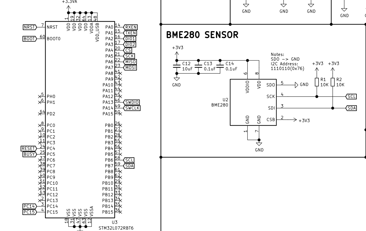
I have a custom board with stm32L072rbt6 and BME280. BME SCL is connected to PB6 (58) and SDA to PB7 (59) on the stm32l0. I am able to read the values from sensor in STM32CubeIDE but now I am trying to get things working with Arduino on PlatformIO.

I used Piconomix PX-HER0 as base since it has same cpu but created custom board setup based on that. I am able to upload code and debug breakpoints but the measurement values are always 0. I can see counter increasing though.

Does anyone know what am I missing here? BME has address 0x76 with SCL & SDA connected to 10k pull-up resistors. I have no leds or serial port on this custom designed board. Only SWD

main.cpp

#include <Wire.h>
#include <Adafruit_Sensor.h>
#include <Adafruit_BME280.h>

Adafruit_BME280 bme;

float temperature, pressure, altitude, humidity;

int i = 0;

void setup()
{
  bme.begin();
}

void loop()
{
  i++;
  temperature = bme.readTemperature();
  pressure = bme.readPressure() / 100.0F;
  humidity = bme.readHumidity();

  delay(2000);
}

platformio.ini

[env:myboard]
platform = ststm32
board = myboard
framework = arduino
debug_tool = stlink
upload_protocol = stlink
debug_port = 127.0.0.1:3333
lib_deps = adafruit/Adafruit BME280 Library@^2.2.4

Thank you in advance!

Did you run the I2C scanner sketch to make sure the Arduino core / Wire library sees an I2C device at all on the bus? https://playground.arduino.cc/Main/I2cScanner/

You also didn’t post your custom board definition, myboard.json. Without that I can’t verify what STM32Duino board variant you’re using, which in turn influences the standard I2C pins it will use.

Sorry! Here are some updates. I have only SWD port available so I am not able to run I2C scanner right?

Here is board definition:
myboard.json

{
  "build": {
    "cpu": "cortex-m0plus",
    "extra_flags": "-DSTM32L072xx",
    "f_cpu": "32000000L",
    "framework_extra_flags": {
      "arduino": ""
    },
    "mcu": "stm32l072rb",
    "product_line": "STM32L072xx",
    "variant": "STM32L0xx/L072R(B-Z)T_L073R(B-Z)T_L083R(B-Z)T"
  },
  "debug": {
    "jlink_device": "STM32L072RB",
    "openocd_target": "stm32l0",
    "svd_path": "STM32L07x.svd"
  },
  "frameworks": [
    "arduino",
    "cmsis",
    "stm32cube",
    "libopencm3"
  ],
  "name": "myboard",
  "upload": {
    "maximum_ram_size": 20480,
    "maximum_size": 131072,
    "protocol": "stlink",
    "protocols": [
      "dfu",
      "serial",
      "jlink",
      "stlink",
      "blackmagic"
    ]
  },
  "url": "https://myboard.com",
  "vendor": "myboard"
}

Well that’s game over right there because with the generic variant you’d be getting

Plus yes you can run the I2C scanner sketch in the debugger and step over each line, just set a breakpoint at

      Serial.print("I2C device found at address 0x");

and check the value of address.

I have also created variants with mainly following updates from Piconomix PX-HER0

variant_MYBOARD.cpp

...
    PB_6, // I2C1_SCL
    PB_7, // I2C1_SDA
...

variant_MYBOARD.h

...
#define PB6 58     /* PX_I2C1_SCL */
#define PB7 59     /* PX_I2C1_SDA*/

#define PX_I2C1_SCL PB6       /* 58 */
#define PX_I2C1_SDA PB7       /*  59 */

// I2C Definitions
#ifndef PIN_WIRE_SCL
#define PIN_WIRE_SCL PB6
#endif
#ifndef PIN_WIRE_SDA
#define PIN_WIRE_SDA PB7
#endif
...

Did you place a

#error "TEST"

in that file to make sure it’s correctly taking that exact file, hence it should not compile? Cause it shouldn’t even look at that file when you don’t reference it like

in your board JSON file.

Yes I can see this when building with that #error

C:\Users\me.platformio\packages\framework-arduinoststm32\variants\STM32L0xx\L072R(B-Z)T_L073R(B-Z)T_L083R(B-Z)T\variant_MYBOARD.cpp:3:2: error: #error “TEST”
3 | #error “TEST”

Okay. Revert that again and place a

#if PIN_WIRE_SCL == PB6
#error "Right pin"
#else
#error "Wrong pin"
#endif

in the src/main.cpp of your project. What does it output?

src\main.cpp:10:2: error: #error “Right pin”
10 | #error “Right pin”

Also

#if PIN_WIRE_SDA == PB7
#error "Right pin"
#else
#error "Wrong pin"
#endif

outputs

src\main.cpp:10:2: error: #error “Right pin”
10 | #error “Right pin”

That seems a bit mystical to me how that works, because nothing should reference variant_MYBOARD.h, but well…

Check in the debugger whether it finds any I2C addresses at all when running the I2C sketch as described previously.

Thank you. I will try to get the I2C scanner working and get back then

I am not 100% sure how should this work but I am using this code

#include <Wire.h>

void setup()
{
  Wire.begin();       // Join I2C bus
  Serial.begin(9600); // Start serial communication at 9600 baud rate
  while (!Serial)
    ; // Wait for serial port to connect - necessary for STM32
  Serial.println("\nI2C Scanner");
}

void loop()
{
  byte error, address;
  int nDevices = 0;

  Serial.println("Scanning...");

  for (address = 1; address < 127; address++)
  {
    // The i2c_scanner uses the return value of the Write.endTransmisstion to see if
    // a device did acknowledge to the address.
    Wire.beginTransmission(address);
    error = Wire.endTransmission();

    if (error == 0)
    {
      Serial.print("I2C device found at address 0x");
      if (address < 16)
        Serial.print("0");
      Serial.print(address, HEX);
      Serial.println("  !");

      nDevices++;
    }
    else if (error == 4)
    {
      Serial.print("Unknown error at address 0x");
      if (address < 16)
        Serial.print("0");
      Serial.println(address, HEX);
    }
  }
  if (nDevices == 0)
    Serial.println("No I2C devices found\n");
  else
    Serial.println("done\n");

  delay(5000); // Wait 5 seconds for the next scan
}

with the breakpoint on
Serial.print("I2C device found at address 0x");
but program never stops on the breakpoint. Instead when manually paused it points to following block

int HardwareSerial::availableForWrite(void)
{
  tx_buffer_index_t head = _serial.tx_head;
  tx_buffer_index_t tail = _serial.tx_tail;       <---- HERE

  if (head >= tail) {
    return SERIAL_TX_BUFFER_SIZE - 1 - head + tail;
  }
  return tail - head - 1;
}

with output:

Program
received signal SIGINT, Interrupt.
HardwareSerial::availableForWrite (this=0x20000738 ) at C:\Users\me.platformio\packages\framework-arduinoststm32\cores\arduino\HardwareSerial.cpp:482
482 tx_buffer_index_t tail = _serial.tx_tail;

Also tried with this code and breakpoint on the delay

#include <Wire.h>

void setup()
{
  Wire.begin();
}

void loop()
{
  volatile byte error;
  byte address;
  static int nDevices = 0;

  nDevices = 0;

  for (address = 1; address < 127; address++)
  {
    Wire.beginTransmission(address);
    error = Wire.endTransmission();

    if (error == 0)
    {
      nDevices++;
    }
  }

  delay(5000);
}

but this can be seen on the inspector after each continue

error: 4 '\004'
address: 127 '\177'
nDevices: 0

Add this object to the “Watch” view and try finding out if it really holds the right SCL and SDA pins in the object’s details.

If I’m checking the correct variables then “NC” does not sound good I guess :thinking:

i2c is a null pointer still. Are you inspecting the Wire object after you’ve called “begin” on it? Otherwise it won’t be validly initialized at all.

I think so since breakpoint is set to last row of loop()

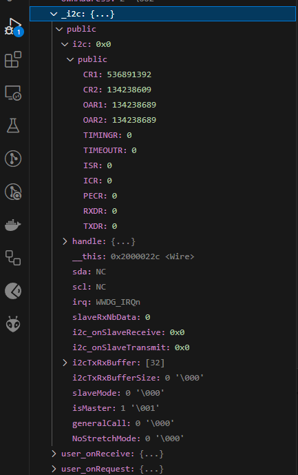
Then step into the Wire.begin() call and look for suspicious things, like returning from the function early because there’s an error in the pinmap or HAL function or whatever.

Did you touch the PeripheralPins.c too? It may e.g. not have that compiled on to know how to map PB7 to the I2C1 peripheral, etc.

Thanks I’ll try that. I did not edit PeripheralPins.c. As far as I understand it should have correct mapping to schematics of my board