Hi again. Sorry for late reply I got blocked to send messages for 24 hour as new account.
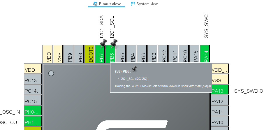
I changed bme.begin(); to Wire.begin(); and now I can see this. Those pin mappings seems a bit strange here. However there does not seem to be any error coming from Wire.begin(); call and it continues the code but gets stuck in the while loop
void setup()
{
  Wire.begin();
  if (!bme.begin())
  {
    Serial.println("Could not find a valid BME280 sensor, check wiring!");
    while (1)
      ;
  }
}
Also I double checked from working STM32CubeIde project and pin mappings with physical pins should be correct in variant file
Please upload your complete project (board definition, variant files, firmware project) somewhere so I can cross check it completely.
Thank you for your effort  Here I created link that has .zip with necessary files Project.zip - pCloud
Thanks, I refactored the project files a lot to be a standalone project (installing board definitions into .platformio seems bad practice to me), and I’ve used Renode to emulate a STM32L072 without actually having your hardware.
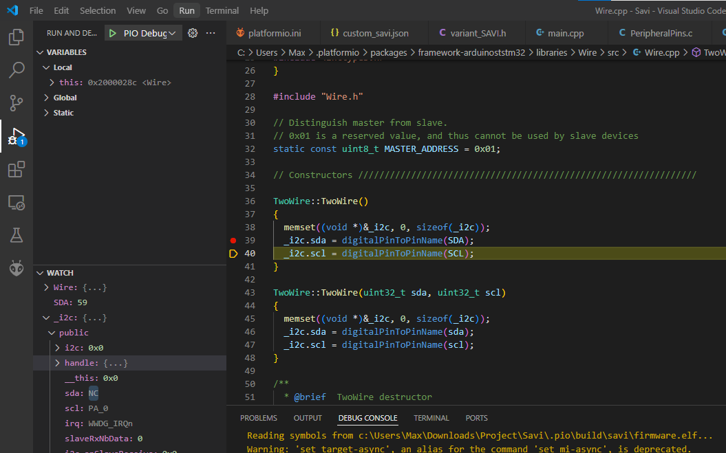
The error is right here.
SDA has a numerical value of 59 (good, that is PIN_WIRE_SDA=PB7=59), but the digitalPinToPinName macro fails to resolve this to the PinName type. Likely because you’ve messed up the conversion array for digital pins inside the variant_SAVI.cpp. I’m checking that now.
/* Note: Analog pin is also a digital pin */
#define digitalPinToPinName(p)      ((((uint32_t)(p) & PNUM_MASK) < NUM_DIGITAL_PINS) ? \
            (PinName)(digitalPin[(uint32_t)(p) & PNUM_MASK] | ((p) & ALTX_MASK)) : \
            (((uint32_t)(p) & PNUM_ANALOG_BASE) == PNUM_ANALOG_BASE) && \
            (((uint32_t)(p) & PNUM_MASK) < NUM_ANALOG_INTERNAL_FIRST) ? \
            (PinName)(digitalPin[analogInputPin[(p) & PNUM_ANALOG_INDEX]] | ((p) & ALTX_MASK)) : NC)
is the definition of that macro. Essentially, digitalPin[(uint32_t)(p)], or via the analogInpuPin arary if it’s an analog pin (above 45).
1 Like
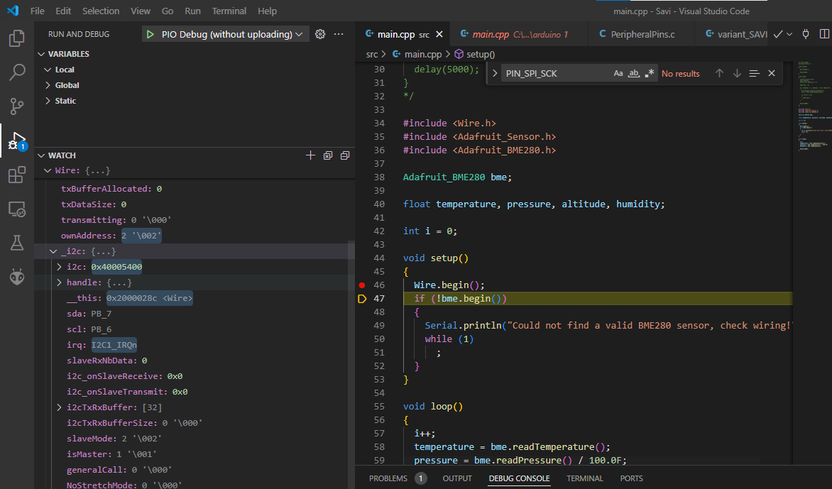
Much better now.
I’ve synced the digitalPins array and the macros (and correct two macros that had really out of place numerical values, they should have been all linearily increasing), and now after Wire.beign(), the SDA and SCL pins do have their correct value.
Let me upload the project…
1 Like
Please try
as a standalone project. You do not need to copy any file anywhere else.
1 Like
Wow that is really amazing. I also did try to include everything in project but VScode just gave errors so I went fast lane. This is much cleaner now. And I did not know you can even emulate hardware 
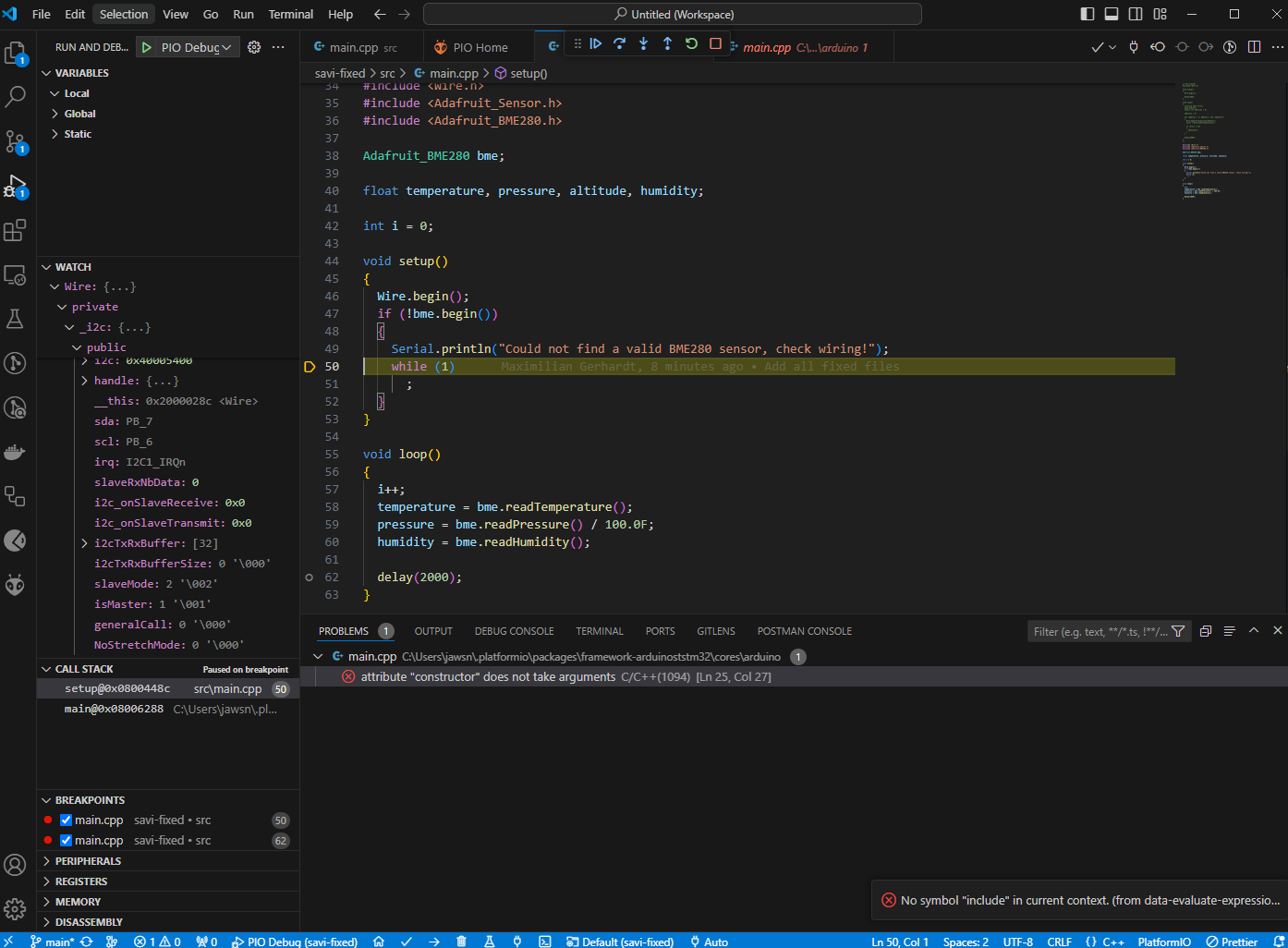
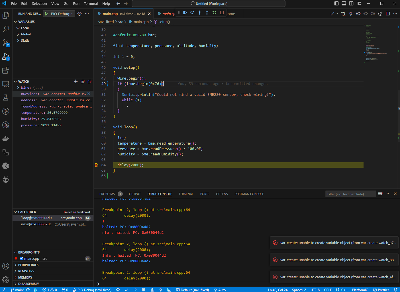
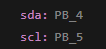
Pins seem correct now when inspecting Wire
But it still seems to be stuck in the while loop not being able to detect BME280
Edit: However I can see the I2C scanner now detecting one device… let me debug more
Does the I2C scanner sketch, when debugging, show any found addresses?
If not, the next step would be to get a logic analyzer (cheap 10$ salae clones) to see if there is any I2C signal at all at PB6, PB7. Depending on whether there is no I2C master activity, or no I2C slave activtiy, the issue is on the microcontroller or BME280 side.
1 Like
Yay now it works! I had to explicitly give the address 0x76 to bme.begin(); call
Absolutely amazing job what you did here. I also learned a lot new things 
1 Like
Good work Max, above and beyond.