I have custom made board with STM32L072RB processor and SX1262 LoRaWAN module. I am trying to find a LoRaWAN library to use with Arduino project in PlatformIO.
What library would you suggest for this? I have been checking multiple well known libs like MCCI LoRaWAN LMIC, Beelan-LoRaWAN and IBM LMIC Framework but as far as I understand those does not work with SX1262 or are not maintained anymore. Also it would be a huge plus if there are some examples for this library.
I would need to be able to join LoRaWAN network using OTAA with a class-A device to submit temperature measurements once every hour and device would be in low-power mode/sleep between submits.
I installed that lib from pio but for some reason when trying to compile I get these errors:
.pio\libdeps\savi\SX126x-Arduino\src\boards\sx126x\sx126x-board.cpp:44:1: error: 'SPISettings' does not name a type

.pio\libdeps\savi\SX126x-Arduino\src\boards\sx126x\sx126x-board.cpp:52:9: error: 'initSPI' was not declared in this scope; did you mean 'init'?
Right. So that library actually implements the base SPI and timers function only for a subset of microcontrollers: nRF52, RP2040, ESP32 and ESP8266 (source). Not STM32.
I’ve attempted to give it a simple implementation using the SPI and STM32 timer libary and enabled debug statements. This makes it compile, but of course I can’t test for sure if it works. Especially unsure about the timers part.
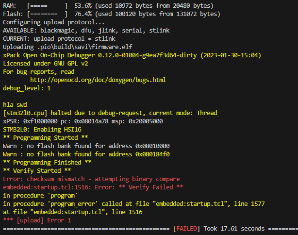
Thank you for providing this example project. However it still seems to either not be able to upload program with following error
Or sometimes when re-opening project it is able to upload the code but it gets stuck in Reset_Handler(): and following errors/warnings are shown in Debug Console
This will still need an implementation for its GPIO, SPI, RTC etc layer, unless you want to take their implementation verbatim, which might conflict with the Arduino implementation (example).
Haha that’s right. I was using new example code but Radiolib in pio library manager was probably updated to new version after I installed it first time.
Managed to get past radio.begin(); and node.beginOTAA(joinEUI, devEUI, nwkKey, appKey); but seems to get stuck on node.activateOTAA();
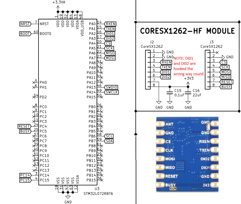
I probably have wrong SPI pin configuration or wrong OTAA join information but I have hard time debugging with only SWD port available
To vreify the pins, have you manually written some code to just use the SPI.h library to read a register from the SX1262? (reset must of course be driven in the right direction for the chip to respond).
I updated my project to use regular lora to start with simpler way of verifying that sending messages work. At the moment I am able to successfully call radio.begin() with following pins when creating radio module:
SX1262 radio = new Module(PA4, PA3, PC4, PC5);
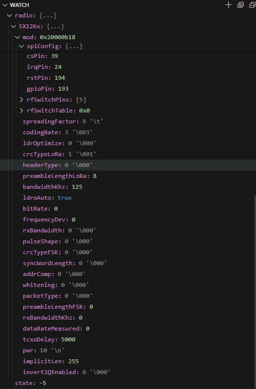
Where PA4 and PC4 were required for this to work. I think this is enough to verify that Radiolib is able to detect my lora module. However I am not able to transmit messages and it will always give status code -5 (RADIOLIB_ERR_TX_TIMEOUT) for state when calling radio.transmit()
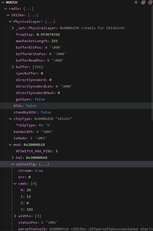
I can inspect following values from radio object in inspector after calling radio.begin()
For some reason chipType says “SX1261” even I am using SX1262
My first assumption is that maybe I have wrong pins declared when creating radio but I don’t understand which should I put there and how is it able to detect lora module with PA4 and PC4 in place