LoRaWAN library for SX1262

Hello.

I don’t really understand how this pin mapping works. For example this PA4 pin is indeed CS pin on my chip but how does this code know that? When hovering over the definition it says that it maps to physical pin 39 (PX_DAC1). I think the correct physical pin would be 20
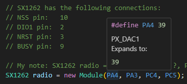
image

In PeripheralPins.c I can find this PA_4 in few places, PinMap_ADC, PinMap_DAC and PinMap_SPI_SSEL (I assume this last is what makes it work)

#ifdef HAL_SPI_MODULE_ENABLED
WEAK const PinMap PinMap_SPI_SSEL[] = {
  {PA_4,  SPI1, STM_PIN_DATA(STM_MODE_AF_PP, GPIO_PULLUP, GPIO_AF0_SPI1)},
  {PA_15, SPI1, STM_PIN_DATA(STM_MODE_AF_PP, GPIO_PULLUP, GPIO_AF0_SPI1)},
  {PB_9,  SPI2, STM_PIN_DATA(STM_MODE_AF_PP, GPIO_PULLUP, GPIO_AF5_SPI2)},
  {PB_12, SPI2, STM_PIN_DATA(STM_MODE_AF_PP, GPIO_PULLUP, GPIO_AF0_SPI2)},
  {NC,    NP,   0}
};
#endif

In variant_SAVI.cpp there is one place with PA_4, // PX_DAC1

Then lastly in variant_SAVI.h there are few places where PA4 is mentioned

// Mapping of STM32 GPIO pin to digital pin number
#define PA4 39     /* PX_DAC1 */

// Mapping of net name to digital pin number
#define PX_SPI1_CS PA4        /* 29 */
#define PX_DAC1 PA4           /* 39 */

// SPI Definitions
#ifndef PIN_SPI_SS
#define PIN_SPI_SS PA4
#endif

But I can find nowhere mapping of PA4 to my chips pin 20 as per schematic. I must be missing something again
Physical pin numbering on the package doesn’t matter at all. What matters is that the code ends up using the right parameters for the STM32 HAL functions. The PA4 macro evaluates to numerical 39 which is translated to a different type by using it as the index in the digitalPin array

And digitalPin[PA4] = diigtalPin[39] = PA_4.

This PinName type value is nothing else but another numerical value

Which means the left 4 bits encode the port number (PortA = 0, PortB = 1, etc,) and hte right 4 bits encode the pin number (e.g. 4).

This byte translated further the needed Port and Pin Name

Through the arrays

So through all these translation layers, it ends up at th eright types for the actual values to use for the STM32HAL, which is (GPIO_TypeDef *) GPIOA_BASE and LL_GPIO_PIN_4. And those exactly control PA4.

So the pin mapping is write. You should also see that if you manually write a blink program for PA4, that it should show up on the oscilloscope.

1 Like

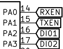
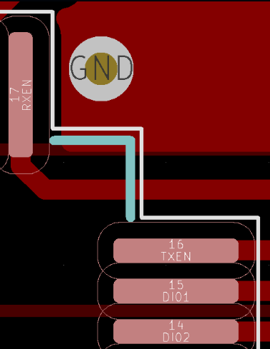
After bashing my head to wall for hours I started to be sure there is something wrong with DIO/Busy pin configurations. So I went to check design files and found out RXEN, TXEN, DIO1 & DIO2 pins where wrongly marked in schematic
image

image

With this pin mapping I was finally able to run lora example :tada:

SX1262 radio = new Module(PA4, PA0, PC4, PC5);

radio.setRfSwitchPins(PA3, PA2);

Thanks for helping me debug this problem!

1 Like