I am struggling to use the Arduino millis() function when I build a project on an ATtiny402.
If I hover over the millis() a window pops up saying #define millis millis Expands to: millis Here millis() is in blue text - as in not a function. Here’s a screen shot
On another board,where I successfully used millis(), the expression expanded to unsigned long millis(). Here millis() is in yellow text - as in a function. Here’s a screen shot
![]()
How do I get the milllis() to initialise correctly with my ATtiny402 board?
I tried to force the use of TCA0 by #define MILLIS_USE_TIMERA0 1
I tried to initialise it by calling init_millis();
Neither of these tactics worked.
I want to use RTC in the project and have the thing run on 32kHz low power oscillator.
Please see full test code here (apologies I am relatively new to PlatformIO, ATtiny402 devices and programming in C/C++ for that matter).
#ifdef F_CPU
#undef F_CPU
#endif
#define F_CPU 32000UL
#include <Arduino.h>
#include <avr/interrupt.h> // so we can use interrupt vector names
#include <util/delay.h> // needed for the delay functions
#define MILLIS_USE_TIMERA0 1 // same result without this
/* pin information
ATtiny402
----u---
VDD| |GND
PWR PA6| |PA3 SIG
SW_M PA7| |PA0 UDIP
BUZ PA1| |PA2 SW_P
--------
*/
#define SIG_bp 3
#define rtc_period 960 // 960 is a rate of 1Hz
void system_init(); // placeholder for compiler
void bop(){ // debug routine
VPORTA_IN |= (1<< SIG_bp); // toggle LED1
_delay_ms(10);
VPORTA_IN |= (1<<SIG_bp); // toggle LED1
}
void setup() {
// put your setup code here, to run once:
system_init();
bop();
init_millis(); // same result without this
}
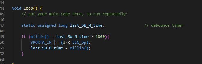
void loop() {
// put your main code here, to run repeatedly:
static unsigned long last_SW_M_time; // debounce timer
if (millis() - last_SW_M_time > 1000){
VPORTA_IN |= (1<< SIG_bp);
last_SW_M_time = millis();
}
}
void mcu_init(void) /* MCU initialization */
{
/* On AVR devices all peripherals are enable from power on reset, this
* disables all peripherals to save power. Driver shall enable
* peripheral if used */
/* Set all pins to low power mode */
for (uint8_t i = 0; i < 8; i++) {
*((uint8_t *)&PORTA + 0x10 + i) |= 1 << PORT_PULLUPEN_bp;
}
}
void pin_init(void){ /* PIN initialization */
/* pin information
ATtiny402
----u---
VDD| |GND
PWR PA6| |PA3 SIG
SW_M PA7| |PA0 UDIP
BUZ PA1| |PA2 SW_P
--------
*/
// define output pins
VPORTA_DIR |= (1<<SIG_bp); // debug
// set output pins LOW
VPORTA_OUT &= ~((1<<SIG_bp)); // debug
}
void CLKCTRL_init(void){ /* Main clock initialization */
/* The following registers have Configuration Change Protection */
// CLKCTRL.MCLKCTRLB
// CLKCTRL.MCLKLOCK
// CLKCTRL.MCLKCTRLA
// CLKCTRL.OSC20MCTRLA
// CLKCTRL.OSC20MCALIBA
// CLKCTRL.OSC20MCALIBB
// CLKCTRL.OSC32KCTRLA
/* Set the Main clock to internal 32kHz oscillator*/
_PROTECTED_WRITE(CLKCTRL.MCLKCTRLA, CLKCTRL_CLKSEL_OSCULP32K_gc);
/* run the 32kHz oscillator in standby mode*/
_PROTECTED_WRITE(CLKCTRL.OSC32KCTRLA, 1 << CLKCTRL_RUNSTDBY_bp);
/* Set the Main clock prescaler divisor to 2X and disable the Main clock prescaler */
_PROTECTED_WRITE(CLKCTRL.MCLKCTRLB, CLKCTRL_PDIV_2X_gc | 0 << CLKCTRL_PEN_bp);
/* ensure 20MHz isn't forced on*/
_PROTECTED_WRITE(CLKCTRL.OSC20MCTRLA, 0 << CLKCTRL_RUNSTDBY_bp);
/* wait for system oscillator changing to finish */
while (CLKCTRL.MCLKSTATUS & CLKCTRL_SOSC_bm) {
}
}
void RTC_0_init(void){ /* Realtime clock initialization */ //- may not need this
/* Wait for all register to be synchronized */
while (RTC.STATUS > 0);
/* 32KHz Internal Ultra Low Power Oscillator (OSCULP32K) */
RTC.CLKSEL = RTC_CLKSEL_INT32K_gc;
/* Period: */
RTC.PER = rtc_period;
/* Compare Match Interrupt disabled, Overflow Interrupt enabled */
RTC.INTCTRL = (0 << RTC_CMP_bp) | (1 << RTC_OVF_bp);
/* Prescaler of 32, enable and run in standby */
RTC.CTRLA = RTC_PRESCALER_DIV32_gc | (1 << RTC_RTCEN_bp) | (1 << RTC_RUNSTDBY_bp);
}
void CPUINT_init(void){ /* Interrupt initialisation */
/* Enable interrupts */
sei();
}
void system_init(){ /* system initialization */
mcu_init();
pin_init();
CLKCTRL_init();
RTC_0_init();
//VREF_0_init();
//ADC_0_initialization();
//EVENT_SYSTEM_0_initialization();
//CPUINT_init();
//SLPCTRL_init();
//BOD_init();
}
ISR(RTC_CNT_vect){ // RTC interrupt
/* Insert your RTC Overflow interrupt handling code */
if (RTC.INTFLAGS & RTC_OVF_bm){
//VPORTA_OUT ^= (1<<SIG_bp); // toggle SIG
}
/* Overflow interrupt flag has to be cleared manually */
RTC.INTFLAGS = RTC_OVF_bm | RTC_CMP_bm;
}
And platformio.ini here
; PlatformIO Project Configuration File
;
;   Build options: build flags, source filter
;   Upload options: custom upload port, speed and extra flags
;   Library options: dependencies, extra library storages
;   Advanced options: extra scripting
;
; Please visit documentation for the other options and examples
; https://docs.platformio.org/page/projectconf.html

[env:ATtiny402]
platform = atmelmegaavr
board = ATtiny402
framework = arduino
upload_speed = 115200
upload_flags =
    --tool
    uart
    --device
    attiny402
    --uart
    $UPLOAD_PORT
    --clk
    $UPLOAD_SPEED
upload_command = pymcuprog write --erase $UPLOAD_FLAGS --filename $SOURCE
It compiles OK but the millis() isn’t returning a meaningful value - I want to use this for some key debounce.
Here’s the compile / load output
 *  Executing task in folder ATtiny402_test copy: C:\Users\Peter\.platformio\penv\Scripts\platformio.exe run --target upload

Processing ATtiny402 (platform: atmelmegaavr; board: ATtiny402; framework: arduino)
---------------------------------------------------------------------------------------------------------------------------------------------------------------------------------------------Verbose mode can be enabled via `-v, --verbose` option
CONFIGURATION: https://docs.platformio.org/page/boards/atmelmegaavr/ATtiny402.html
PLATFORM: Atmel megaAVR (1.6.0) > ATtiny402
HARDWARE: ATTINY402 16MHz, 256B RAM, 4KB Flash
PACKAGES:
 - framework-arduino-megaavr-megatinycore @ 2.5.11
 - tool-avrdude-megaavr @ 3.60300.220118 (6.3.0)
 - toolchain-atmelavr @ 3.70300.220127 (7.3.0)
LDF: Library Dependency Finder -> https://bit.ly/configure-pio-ldf
LDF Modes: Finder ~ chain, Compatibility ~ soft
Found 15 compatible libraries
Scanning dependencies...
No dependencies
Building in release mode
Compiling .pio\build\ATtiny402\src\main.cpp.o
Linking .pio\build\ATtiny402\firmware.elf
Checking size .pio\build\ATtiny402\firmware.elf
Advanced Memory Usage is available via "PlatformIO Home > Project Inspect"
RAM:   [=         ]   5.5% (used 14 bytes from 256 bytes)
Flash: [==        ]  15.4% (used 632 bytes from 4096 bytes)
Building .pio\build\ATtiny402\firmware.hex
Configuring upload protocol...
AVAILABLE: jtag2updi
CURRENT: upload_protocol = jtag2updi
Looking for upload port...
Auto-detected: COM7
Uploading .pio\build\ATtiny402\firmware.hex
Connecting to SerialUPDI
Pinging device...
Ping response: 1E9227
Erasing device before writing from hex file...
Writing from hex file...
Writing flash...
Done.
Any help would be much appreciated.