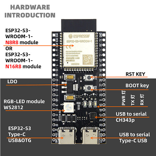
How do you set up a new board ESP32-S3 N16R8

Hi, I’m new to this, I have just read a topic about the new esp32-s3 n16r8 board and it is not clear to me how this is done. ie add the board to PlatformIO what to put in the platformio.ini file.
Also what is ‘xtensa-esp32s3-elf-g++’ is not recognized as an internal or external command,
Is there any more information that’s available so I can try this board?
(Have used the Doit ESP32 on PlatformIO with no problems)
Hope some one can help.

many thanks

I’m trying to figure this out too. I asked Espressif if they support Platform IO for their boards, and they said no. Which makes me wonder if PIO is the right path.

Did you figure this out?

Take a look at this:
https://docs.platformio.org/en/latest/platforms/creating_board.html


None of these threads had the right config for you? Two of them are marked as solved…

Just managed to get it to work, found esp32-s3-devkitc-1 - n16r8v.json file on github and copied it to the ,platformio/platforms/expressif32/boards folder. and created a new Project in Platformio and used that board.

platformio.ini:
[env:esp32-s3-devkitc-1 - n16r8v]
platform = espressif32
board = esp32-s3-devkitc-1 - n16r8v
framework = arduino
monitor_speed = 115200

lib_deps = FASTLED


main.cpp:

#include <Arduino.h>
#include <FastLED.h>

#define NUM_LEDS 1
#define DATA_PIN 48
int i=0;

CRGB leds[NUM_LEDS];

void setup() {
FastLED.addLeds<SK6812, DATA_PIN, GRB>(leds, NUM_LEDS);
Serial.begin(115200);
}

void loop() {
if (i != 4){

for (i=0; i<4; i++){

  leds[0] = CRGB::Red;
  FastLED.show();
  Serial.println("RED LED is ON");
  delay(500);
  leds[0] = CRGB::Green;
  FastLED.show();
  Serial.println("GREEN LED is ON");
  delay(500);
  leds[0] = CRGB::Blue;
  FastLED.show();
  Serial.println("BLUE LED is ON");
  delay(500);
  leds[0] = CRGB::Black;
  FastLED.show();
  Serial.println("LED's are OFF");
  delay(1500);
}

}
}

Part of upload:

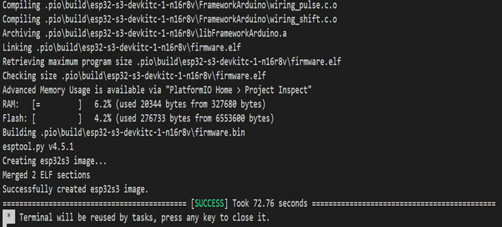
Linking .pio\build\esp32-s3-devkitc-1 - n16r8v\firmware.elf
Retrieving maximum program size .pio\build\esp32-s3-devkitc-1 - n16r8v\firmware.elf
Checking size .pio\build\esp32-s3-devkitc-1 - n16r8v\firmware.elf
Advanced Memory Usage is available via “PlatformIO Home > Project Inspect”
RAM: [= ] 5.9% (used 19324 bytes from 327680 bytes)
Flash: [ ] 3.8% (used 251873 bytes from 6553600 bytes)
Building .pio\build\esp32-s3-devkitc-1 - n16r8v\firmware.bin
esptool.py v4.4

Hope that helps…

1 Like

Here’s the link I found.

This is from the Espressif’s web site. PlatformIO - ESP32 - — ESP-IDF Programming Guide latest documentation . I posted in their forums questions with platformio/espidf projects.

Hi, Long time but I have changed the Board .json file and have this result…

This is my Platform.ini file:
image

esp32-s3-devkitc-1-n16r8v.json file:

{
  "build": {
    "arduino":{
      "ldscript": "esp32s3_out.ld",
      "partitions": "default_16MB.csv"
    },
    "core": "esp32",
    "extra_flags": [
      "-DARDUINO_ESP32S3_DEV",
      "-DARDUINO_USB_MODE=1",
      "-DARDUINO_RUNNING_CORE=1",
      "-DARDUINO_EVENT_RUNNING_CORE=1"
    ],
    "f_cpu": "240000000L",
    "f_flash": "80000000L",
    "flash_mode": "qio",
    "hwids": [
      [
        "0x303A",
        "0x1001"
      ]
    ],
    "mcu": "esp32s3",
    "variant": "esp32s3"
  },
  "connectivity": [
    "wifi"
  ],
  "debug": {
    "default_tool": "esp-builtin",
    "onboard_tools": [
      "esp-builtin"
    ],
    "openocd_target": "esp32s3.cfg"
  },
  "frameworks": [
    "arduino",
    "espidf"
  ],
  "name": "Espressif ESP32-S3-DevKitC-1-N16R8V (16 MB QD, No PSRAM)",
  "upload": {
    "flash_size": "16MB",
    "maximum_ram_size": 327680,
    "maximum_size": 16777216,
    "require_upload_port": true,
    "speed": 460800
  },
  "url": "https://docs.espressif.com/projects/esp-idf/en/latest/esp32s3/hw-reference/esp32s3/user-guide-devkitc-1.html",
  "vendor": "Espressif"
}

Hope that helps?

1 Like

I’ve followed the various examples and build is working ok but I’m having an issue uploading to the board over the COM/UART port. I keep getting Operation timed out. Perhaps I’m doing (or not doing) something dumb. Does anyone have any tips?

The log would have been interesting here.

Have you tried to put the board into upload mode manually* and then started the upload?

* Press and hold the BOOT button, press the RST button, release the BOOT button

Thanks for the suggestion, though same result with various combinations of BOOT and RESET during power on or while powered on. Here is my log:

*  Executing task: platformio run --target upload --target monitor --environment esp32-s3-n16r8 

Processing esp32-s3-n16r8 (platform: espressif32; board: esp32-s3-devkitc-1-n16r8v; framework: arduino)
----------------------------------------------------------------------------------------------------------------------
Verbose mode can be enabled via `-v, --verbose` option
CONFIGURATION: https://docs.platformio.org/page/boards/espressif32/esp32-s3-devkitc-1-n16r8v.html
PLATFORM: Espressif 32 (6.6.0) > Espressif ESP32-S3-DevKitC-1-N16R8V (16 MB QD, 8MB PSRAM)
HARDWARE: ESP32S3 240MHz, 320KB RAM, 16MB Flash
DEBUG: Current (esp-builtin) On-board (esp-builtin) External (cmsis-dap, esp-bridge, esp-prog, iot-bus-jtag, jlink, minimodule, olimex-arm-usb-ocd, olimex-arm-usb-ocd-h, olimex-arm-usb-tiny-h, olimex-jtag-tiny, tumpa)
PACKAGES: 
 - framework-arduinoespressif32 @ 3.20014.231204 (2.0.14) 
 - tool-esptoolpy @ 1.40501.0 (4.5.1) 
 - tool-mkfatfs @ 2.0.1 
 - tool-mklittlefs @ 1.203.210628 (2.3) 
 - tool-mkspiffs @ 2.230.0 (2.30) 
 - toolchain-riscv32-esp @ 8.4.0+2021r2-patch5 
 - toolchain-xtensa-esp32s3 @ 8.4.0+2021r2-patch5
LDF: Library Dependency Finder -> https://bit.ly/configure-pio-ldf
LDF Modes: Finder ~ chain, Compatibility ~ soft
Found 33 compatible libraries
Scanning dependencies...
No dependencies
Building in release mode
Retrieving maximum program size .pio/build/esp32-s3-n16r8/firmware.elf
Checking size .pio/build/esp32-s3-n16r8/firmware.elf
Advanced Memory Usage is available via "PlatformIO Home > Project Inspect"
RAM:   [=         ]   5.8% (used 19040 bytes from 327680 bytes)
Flash: [          ]   4.0% (used 261521 bytes from 6553600 bytes)
Configuring upload protocol...
AVAILABLE: cmsis-dap, esp-bridge, esp-builtin, esp-prog, espota, esptool, iot-bus-jtag, jlink, minimodule, olimex-arm-usb-ocd, olimex-arm-usb-ocd-h, olimex-arm-usb-tiny-h, olimex-jtag-tiny, tumpa
CURRENT: upload_protocol = esptool
Looking for upload port...
Auto-detected: /dev/cu.usbmodem579A0184651
Uploading .pio/build/esp32-s3-n16r8/firmware.bin
esptool.py v4.5.1
Serial port /dev/cu.usbmodem579A0184651
Connecting...
Chip is ESP32-S3 (revision v0.2)
Features: WiFi, BLE
Crystal is 40MHz
MAC: dc:da:0c:2a:0a:14
Uploading stub...

A fatal error occurred: Failed to write to target RAM (result was 01070000: Operation timed out)
*** [upload] Error 2
============================================= [FAILED] Took 4.14 seconds =============================================

I remember there was a similar post a few days ago. But i don’t remember the exact reason. Wrong device, wrong driver, missing rights…

Why is MacOS using such cryptic names?!? …

Yeah I don’t know, I got this on Amazon hoping it would be similar to one a customer of mine is using but it’s different and there is no documentation. Buyer beware. I put it on my Linux system and dmesg shows the “COM” port coming up as USB Single Serial ACM device, and “USB” port as USB JTAG/serial debug from Espressif. Which I think is backwards to other similar boards I’ve seen. It does seem to load firmware over the “USB” port but it won’t serial monitor and the LED blink isn’t working so I’m not exactly sure what it’s doing post-flash.

Which setup do you use? please show the conent of your platformio.ini (and the used board json file if it is a non standard one from the platform itself).

Which board do you have exactly?

Thanks for your help. I think my main issue is not having any docs for the board. The “USB” port which on most similar boards is not the programming port, does accept the upload and a recent retry I get the serial output message (LED blink must be a coding problem or bad GPIO reference). Which now leaves me wondering what the “COM” port is, which I was expecting to be the JTAG with the other being USB/UART bridge…

I have a couple different setup options. One is a Mac Mini M1 (Monterey 12.7.5) the other is Intel x86_64 Debian-based (Mint 20.3). The board I bought is called DWEII ESP32-S3-DevKitC-1-N16R8 from Amazon.ca.

ini file:

[env:esp32-s3-n16r8]
platform = espressif32
board = esp32-s3-devkitc-1-n16r8v
framework = arduino

board json file (as linked in the thread above):

{
    "build": {
      "arduino":{
        "ldscript": "esp32s3_out.ld",
        "partitions": "default_16MB.csv",
        "memory_type": "qio_opi"
      },
      "core": "esp32",
      "extra_flags": [
        "-DARDUINO_ESP32S3_DEV",
        "-DBOARD_HAS_PSRAM",
        "-DARDUINO_USB_MODE=1",
        "-DARDUINO_USB_CDC_ON_BOOT=1"
      ],
      "f_cpu": "240000000L",
      "f_flash": "80000000L",
      "flash_mode": "qio",
      "psram_type": "opi",
      "hwids": [
        [
          "0x303A",
          "0x1001"
        ]
      ],
      "mcu": "esp32s3",
      "variant": "esp32s3"
    },
    "connectivity": [
      "wifi",
      "bluetooth"
    ],
    "debug": {
      "default_tool": "esp-builtin",
      "onboard_tools": [
        "esp-builtin"
      ],
      "openocd_target": "esp32s3.cfg"
    },
    "frameworks": [
      "arduino",
      "espidf"
    ],
    "name": "Espressif ESP32-S3-DevKitC-1-N16R8V (16 MB QD, 8MB PSRAM)",
    "upload": {
      "flash_size": "16MB",
      "maximum_ram_size": 327680,
      "maximum_size": 16777216,
      "require_upload_port": true,
      "speed": 921600
    },
    "url": "https://docs.espressif.com/projects/esp-idf/en/latest/esp32s3/hw-reference/esp32s3/user-guide-devkitc-1.html",
    "vendor": "Espressif"
  }

main.cpp is pretty basic:

#include <Arduino.h>

// #define LED_BUILTIN 48

void setup() {
  Serial.begin(115200);
  delay(500);
  Serial.println("Starting");
}

void loop() {
  digitalWrite(RGB_BUILTIN, (millis() / 1000) % 2);
}
Okay.

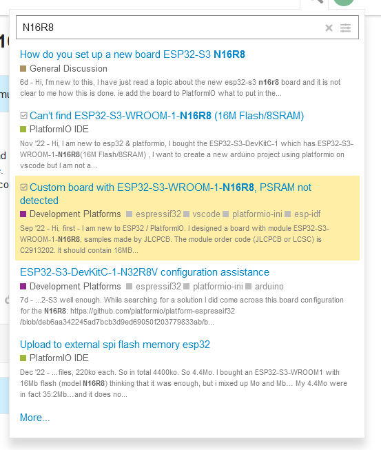
This board comes with 2 USB ports.
The one below the RGB LED is the native USB.
The other one is UART.

Your board .json defines USB_MODE=1 and USB_CDC_ON_BOOT=1
This means Serial object is routed to the native USB (HWCDC).
See ESP32-S3 native USB interface and Serial Monitor missing first messages - #10 by sivar2311

That might be the reason you don’t see anything on the serial monitor.
If you use the UART USB connector, your code must use Serial0.

Take a look beside the RGB LED.
There is a soldering bridge you might need to close to get the on board RGB-LED to work.

Yep got it now, thanks very much. The soldering bridge is there, the LED trick was the RGB_BUILTIN is on 48 not the default (49?).

I’m curious did you find some information on the board that my searching missed? Or just derived it from my info above in the post?

But 48 is “default”!

Which one do you mean exactly?
About the serial / serial0 object? That was taken from your board json file.

Hmm…my pins_arduino is slightly different (maybe needs an update) but effectively the same. Strange it didn’t seem to flash the LED unitl I explicitly defined RGB_BUILTIN 48 in main.cpp.

What I meant was how you identified that the port under the LED is the native UART did you find a document or just from the info I provided from the dmesg.

I’m very new to the board.json files but your other post mentioned was helpful, thanks again.

My board is labled on the bottom side “COM” and “USB”.
The small square chip on the upperside is the CH343.

I have the YD-ESP32 and there is a repo with a lot of useful informations:

Awesome thanks. My board looks the same. I had watched a video about the YD that led me a bit astray as I interpreted that it said the “COM” port is the one used for programming. At least now I can play around with it a bit and try some different settings until I better understand your other post :). But for now this has me moving ahead so thank you again!

2 Likes