Hi I have read the 4809 datasheet (well, parts of it) and it states that a fuse must be set to enable the H/W reset;
12.3.2.1.4 External Reset
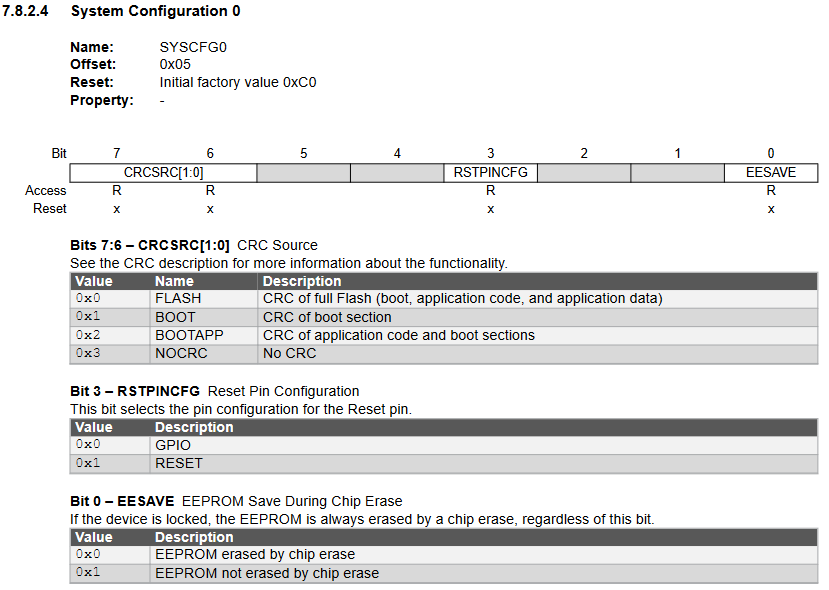
The external Reset is enabled by a fuse, see the RSTPINCFG field in FUSE.SYSCFG0.
When enabled, the external Reset requests a Reset as long as the RESET pin is low. The device will stay in Reset
until RESET is high again
I think this explains why my hardware reset button doesn’t work currently. I’m still finding my way with AVR, so could anyone help me with setting the required fuse?
I’m using PyUPDI as my programming tool currently.
Okay so first of all, disclamer, I’ve read https://www.avrfreaks.net/comment/2489816#comment-2489816 where someone says reconfiguring the reset pin as RESET instead of GPIO makes UPDI programming work, and a comment directly underneath saying that that is not true. I haven’t done any tests myself, so proceed with caution.
Per datasheet page 56 the bit-structure of the releant SYSCFG0 fuse is
So the initial factor value of 0xC0 has the third bit (RSTPINCFG) set to 0, which makes it a GPIO.
If nothing else in regards to the initial factory configuration is to be changed, the new value would be 0xC0 | (1 << 3) = 0xc8 (setting the third bit to make RSTPINCFG = 1 and thus a RESET) for the SYSCFG0 fuse.
The documentation tells you how to set the fuse bits manually to the previously calculated value.
If I look at your previous configuration you’re however using a custom upload protocol (pyupdi) which means you can’t actually make use of automatic fuse calculation and uploading, as that is intended for the avrdude upload program (source). Otherwise you could have added
board_build.f_cpu = 20000000L
board_hardware.oscillator = internal
board_hardware.uart = no_bootloader
; RST pin is either reset or gpio
board_hardware.rstpin = reset
to the config and ran pio run -t fuses.
So since that will not be working, you have to set the fuses manually by invoking PyUPDI. The program is well-capable of setting fuses
Since we know from the datasheet that SYSCFG0 has offset 0x5 (also decimal 5) in the fuses and the new value for it should be 0xc8, we can construct a PyUPDI command that sets that fuse to the desired value.
execute pyupdi -d atmega4809 -c COM12 -b 115200 -fr to read out all fuses. Note them down somewhere so that you have your old fuse values to get back to if something fails. This also checks the conenction to the target AVR chip. Double check that the original value of the 5th fuse is the expected 0xc0 – otherwise SYSCFG0 may be numbered as “Fuse 6” maybe.
try the set fuse command above.
check whether reset (pin PF6) is now functioning as expected.
That’s uhh… really interesting? The default value for the fuses should be, per datasheet:
Offset 0: 0x00
Offset 1: 0x00
Offset 2: 0x02
Offset 3: ? (not mentioned)
Offset 4: ? (not mentioned)
Offset 5: 0xC0
Offset 6: 0x07
Offset 7: 0x00
Offset 8: 0x00
Offset 9: ? (not mentioned)
Offest 10: 0xC5
So the fith fuse definitely had a non-standard value even before you changed it. The rest of the fuses seem to match up all perfectly with the default values.