Serial problem on a mega4809

I’m a bit stumped by this problem and I must have missed something. Thanks for any advice.

I have a project set up and working on an AVR mega4809 DIP on breadboard - 40 pin variant. The pinouts I have used are here4809 DIP 40 pinout:

The 4809 pins TXD1 and RXD1 are connected to an FTDI chip the Serial1 baud rate is set to 19200 and the monitor speed is also set to 19200 as per PIO.ini below.

I can send and receive via the PIO serial monitor.

So now comes the problem.

I rejigged the serial pin connections on the breadboard to use TXD0 and RXD0 and changed all references to ‘Serial1’ in my code to ‘Serial’ (there are only four references)

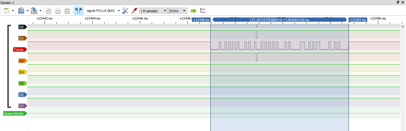
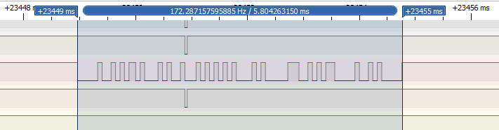
As a result of this action the output from the chip to the PIO serial monitor is garbled, the result of

void loop()
{
  //todo remove following line
Serial.println("HERE");

is shown below.

legacy Click
--- Available filters and text transformations: colorize, debug, default, direct, hexlify, log2file, nocontrol, printable, send_on_enter, time
--- More details at http://bit.ly/pio-monitor-filters
--- Miniterm on COM12  19200,8,N,1 ---
--- Quit: Ctrl+C | Menu: Ctrl+T | Help: Ctrl+T followed by Ctrl+H ---
"KHID�C�V*D�im␑D�im␑D�im␑D�i)␑D�im␑D�ii␑D�im␑D�im␑D�im␑D�i)␑D�im␑D�ii␑D�im␑D�ii␑D�im␑D�im␑D�ii␑D�i)␑D�im␑D�im␑D�i)␑D�im␑D�im␑D�im␑D�im␑D�ii␑D�im␑D�ii␑D�im␑D�im␑D�i)␑D�im␑D�i)␑D�im␑D�i)␑D�im␑D�ii␑D�im␑D�ii␑D�im␑D�ii␑D�im␑D�ii␑D�im␑D�im␑D�i)␑D�im␑D�i)␑D�im␑D�ii␑D�im␑D�ii␑D�im␑D�ii␑D�im␑D�ii␑D�im␑D�i)␑D�im␑D�ii␑D�im␑D�im␑D�im␑D�im␑D�im␑D�ii␑D�im␑D�im␑D�im␑D�im␑D�im␑D�ii␑D�im␑D�im␑D�im␑D�ii␑D�im␑D�im␑D�i)␑D�im␑D�im␑D�im␑D�ii␑D�i)␑D�im␑D�im␑D


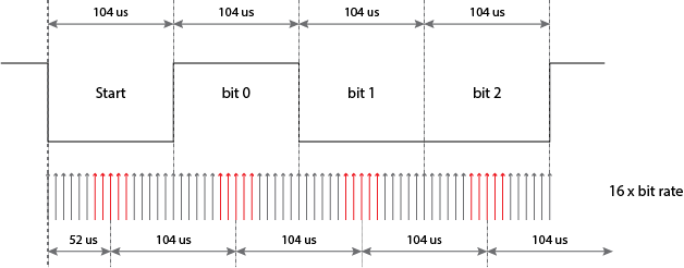
So normally I would think this is a baud rate issue (in my experience that’s often the cause), but I’ve checked and it’s 19200 in setup()

Serial.begin(19200);    // with ASCOM driver refer to DIP 40 pinout to get correct pin numbers for all the serial ports - see the google doc - 'Pin config for Radio Encoder MCU'
  Serial1.begin(19200);   // with stepper MCU - change this to Serial1 when coding for 4809, see google doc - Pin config for Radio Encoder MCU
  Serial2.begin(19200);   // with monitor program Change to Serial2 when coding for 4809,    see google doc - Pin config for Radio Encoder MCU


I’ve tried changing baud rate in the code to 9600 (also in PIO.ini of course), but the result is the same.

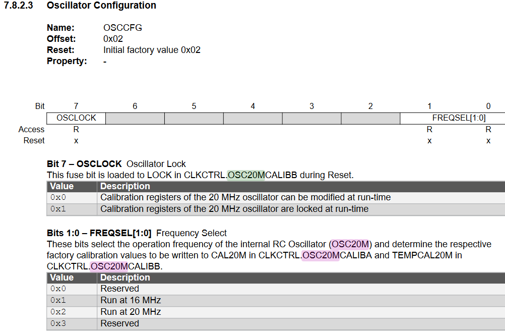
As I’m using the arduino framework for this project, I assume I don’t have to set the chip clock speed?

I’ve also double checked the hardware pin connections and swapped out the FTDI chip for a new one.

thanks for any thoughts on this

PIO.ini below

[env:ATmega4809]
board               = ATmega4809
platform            = atmelmegaavr
framework           = arduino
board_build.variant = 40pin-standard
monitor_flags = 
	--echo


upload_protocol = custom
upload_speed = 115200
upload_port = COM12
upload_flags = 
    -d
    atmega4809
    -c
    $UPLOAD_PORT
    -b
    $UPLOAD_SPEED
upload_command = pyupdi $UPLOAD_FLAGS -f $SOURCE

; Serial monitor baud rate
monitor_port = COM12
monitor_speed = 19200


[platformio]
description = The integrated Azimuth Encoder


Can you do a quick test where you montitor for half or double the baud rate set up in the code? E.g., monitor_speed = 9600 when Serial.begin(19200); is used, etc. There might be some issues in the clock generation of selection.

thanks for help, I tried monitor_speed = 38400 and monitor_speed = 9600, but no difference.

I have added a simple blink led section, just to ensure the code is running and that has confirmed with a led blnk every second as set in the code


void loop()
{
  //todo remove following line
Serial.println("HERE");

digitalWrite(7,LOW);
delay(1000);
digitalWrite(7,HIGH);
delay(1000);

I now have Serial1 connected to a different FTDI, I’ll just check that’s working and post back.

all the serial ports (0,1,2) produce the same garbled result. It must be something I’ve done, so I’ll go back to a different 4809 with a different ftdi and build a basic serial input output function.

This is really strange as I keep my code version controlled on github and it worked at each test, but I had only coded up the section that used Serial1, perhaps I’ll revert back.

I’ll post back once I’ve got somewhere…
thanks.

OK, so I feel I have proved the wiring hardware connections are correct, because I loaded a baremetal project which comms over USART1 and that works as expected over the serial monitor - send some chars, receive some back.

What I did next was create a completely new PIO project and copy the baremetal PIO.ini into it, just changing the monitor_speed from 9600 to 19200 to match the code below.
then I wrote this:

#include <Arduino.h>
#define ledpin 7

void setup() 
{
  // put your setup code here, to run once:


// notes for serial comms - 
  Serial.begin(19200);    // with ASCOM driver refer to DIP 40 pinout to get correct pin numbers for all the serial ports - see the google doc - 'Pin config for Radio Encoder MCU'
  Serial1.begin(19200);   // with stepper MCU - change this to Serial1 when coding for 4809, see google doc - Pin config for Radio Encoder MCU
  Serial2.begin(19200);   // with monitor program Change to Serial2 when coding for 4809,    see google doc - Pin config for Radio Encoder MCU


}  // end setup

void loop() 
{
  digitalWrite(ledpin,LOW);
  delay(1000);
  digitalWrite(ledpin,HIGH);
  delay(1000);
  
  Serial1.println("HERE");

}  //end loop

Which compiles and uploads fine, the led blinks. However, Serial1 still produces garbled output:

egacy Click
--- Available filters and text transformations: colorize, debug, default, direct, hexlify, log2file, nocontrol, printable, send_on_enter, time
--- More details at http://bit.ly/pio-monitor-filters
--- Miniterm on COM12  19200,8,N,1 ---
--- Quit: Ctrl+C | Menu: Ctrl+T | Help: Ctrl+T followed by Ctrl+H ---
D�im␑D�im␑D�im␑D�im␑D�im␑D�im␑D�im␑D�im␑D�im␑D�im␑D�i)␑D�ii␑
--- exit ---

Terminal will be reused by tasks, press any key to close it.

PIO.ini below:


[env:ATmega4809]
board               = ATmega4809
platform            = atmelmegaavr
framework           = arduino
board_build.variant = 40pin-standard
monitor_flags = 
	--echo


upload_protocol = custom
upload_speed = 115200
upload_port = COM12
upload_flags = 
    -d
    atmega4809
    -c
    $UPLOAD_PORT
    -b
    $UPLOAD_SPEED
upload_command = pyupdi $UPLOAD_FLAGS -f $SOURCE

; Serial monitor baud rate
monitor_port = COM12
monitor_speed = 19200


[platformio]
description = The integrated Azimuth Encoder


Any help much appreciated.

Just for the hell of it, I’ll change the baud rate to 9600 and if that works, I’ll post back. No breath holding allowed…

still the same when changed to 9600 :frowning:

I also tried 115200 baud (in code and changed in pio.ini) as the code uploads using that, but still garbled output on serial monitor.

If there’s anything else you’d like me to try, please let me know.

thanks again for help.

  • How is the 4809 connected ot the breadboard?
  • What is its clock source?
  • What fuses does it have set?
  • If you have a cheap logic analyzer (example), you can trace the signal and immediately see the baud rate (frequency) of the UART TX signal. Is that possible?

Point 1 - It’s connected via a zif socket, but bear in mind if I load my baremetal code and change NOTHING in wiring/ hardware, the serial comms work as expected over USART1
point 2 - clock source is internal clock
Point 3 - sorry I don’t know, I have neve changed these, but if there’s a way to find them out, I can post
point 4 - I’ll have a think about that.

thanks for help,
Paul

I bought a logic analyzer a whle back but not used it yet. It’s the same type as your link 24MHz 8ch uses sigrok pulseview. I’ll try it out and see what I can find out.
thanks.

ok so I’ve got the logic analyzer set up and showing a square wave pulse train for the led flashing on PA7…now to find out how to measure frequency. I’ll post back findings on the Tx pin

Let me know if you need help. The UART TX pin signal should look something like

It idles HIGH then pulls the signal low and starts transmitting bits at the preconfigured baud rate. The width of the smallest pulse lets you determine the baud. In the example above, we can e.g. see the start bit is 104µS long, which translates (through frequency = 1 / period) to ~9600Hz, aka 9600 baud. (calculator). The logic analyzer program (like, “Logic” by Salae or “PulseView”, depending on the logic analyzer) should let you view the width of the pulse, or even directly translate it to frequency.

thanks for that, it’s a long time since I used an oscilloscope and got involved in trace analysis.

I monitored the Tx line with the code baud rate set at 9600 so that sampling the Tx line at 25kHz would work well enough (?) in my screenshot below it doesn’t look like the bit periods are uniform which is probably the problem. But, why doesn’t this problem manifest when I laod my baremetal project? It’s almost like as if the baud rate isn’t set. Anyway, I’m new to the logic analyzer stuff, so probably missed something.
thanks very much for detailed help, I appreciate it.

better screenshot:

That’s the whole transmission, what’s the length of one of these small pulses (1 bit) in the middle? You can zoom further in and drag the markers to the left and right at one of these pulses

looks like 80 uS, so 12500 baud:

So I left the code at 9600 baud and changed the monitor_speed = 12500

and now the serial monitor is no longer garbled :slight_smile: :

legacy Click
--- Available filters and text transformations: colorize, debug, default, direct, hexlify, log2file, nocontrol, printable, send_on_enter, time
--- More details at http://bit.ly/pio-monitor-filters
--- Miniterm on COM12  12500,8,N,1 ---
--- Quit: Ctrl+C | Menu: Ctrl+T | Help: Ctrl+T followed by Ctrl+H ---
HERE0
HERE0
HERE0
HERE0
HERE0
HERE0

--- exit ---

Terminal will be reused by tasks, press any key to close it.

That’s obviously good information, but what does that tell us?

Thanks again

So the processor (or at least the code running the UART output) factor ~1.3 faster than it’s supposed to be. Hm.

The board information for board = ATmega4809 says

But if you’re running on the internal clock without any modifications then the datasheet says…

that’s 20 MHz (default 0x02 option applies).

And 20MHz compared to 16MHz is 1.25 times as fast, seems close the observed 1.3.

Can you add

board_build.f_cpu = 20000000L

to the platformio.ini to tell the build system your chip is running at 20MHz? Does the signal then come out as actual 9600 baud if you tell it in code to do 9600 baud?

Thanks for the info and with that mod, it works with baud in code at 9600, monitor speed at 9600

Thanks for all the help to get to this point.

I am really puzzled now, as I have been developing this application for a few months. I used Serial1 as I mentioned previously and I have many working commits on github. It’s only when I got to coding up the other comms lines and as part of that changed from Serial1 to Serial, that it folded.

So it’s great to have a solution, but not great to know why that change is necessary part way through a project.

I wouldn’t have solved this by myself, so much appreciate your help. I guess I’ll keep the new clock and see how things progress.

Or did you change the programm uploader tool in the meantime? (pyupdi isn’t standard). Maybe you exchanged the chip that had different / the default fuses?

In any case, MegaCoreX/PlatformIO.md at master · MCUdude/MegaCoreX · GitHub also mentions all relevant PlatformIO settings, including f_cpu that was needed here. It also talks about burning fuses and a bootloader onto the chip (which might set the initially expected fuses for 16MHz).

But of course it’s more advantegous to run the chip at 20MHz rather than 16MHz for speed, so if that’s the default fuse settings with no modifications you should definitely go with that.

good point, I was using a microUPDI previously, but wasn’t aware that would make changes to chip defaults, so didn’t mention it in the above discussion. I used that for all the successful github commits.

So changing to pyUPDI, i uploaded my bare (ish) metal project where the comms worked, and that had these lines in the header file (probably from the Microschip samples, but not sure):

#define F_CPU 3333333
#define USART1_BAUD_RATE(BAUD_RATE) ((float)(F_CPU * 64 / (16 * (float)BAUD_RATE)) + 0.5)
#define INIT_DELAY			10	// Delay to invalidate the after-reset noise on the PC0 pin (TX) 

so I guess that explains why that code worked

Thanks also for the link, I’ll explore that and use it as a future reference.