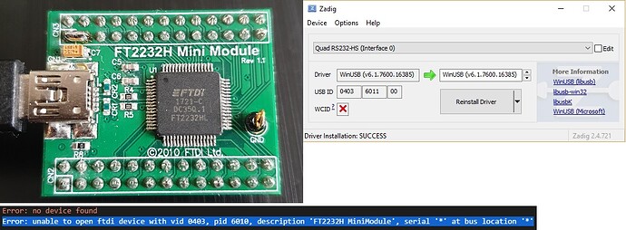
HI, so moving on from my attempts with the slow FT232R, I have taken delivery of an FT2232H Mini Module and gone through setting it up, tiny problem though and i hope the attached image explains it, essentially the FTDI Mini Module has a USB ID of 0x403 0x6011 rather than the 0x403 0x6010 that the debugger is expecting, I’m pretty sure this should be fixable by changing 0x6010 to 0x6011 in an CFG file somewhere, just not sure where that file is.
C:\Users\[user]\.platformio\packages\tool-openocd-esp32\share\openocd\scripts\interface\ftdi\minimodule.cfg
 Cheers all , found it!
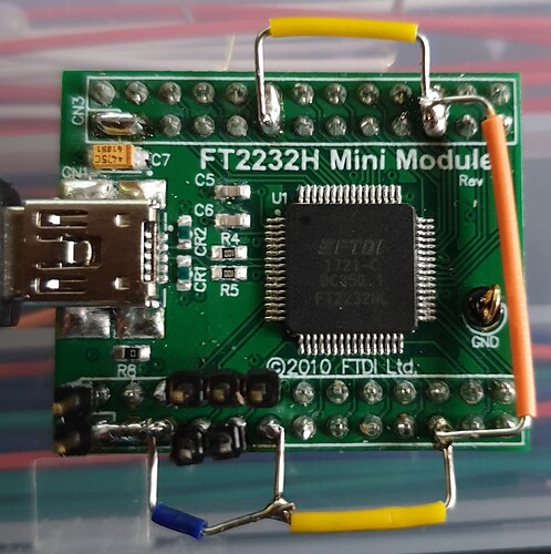
Fair bit of electrical configuration required for this particular PCB design namely the FT2232H Mini Module Rev 1.1 (c) 2010 FTDI Ltd.
[Update]
I can confirm this setup is able to debug the ESP32 perfectly at 20Mhz!
NOTE: When correctly wired as below and the WinUSB drivers installed with Zadig onto FT2232H MiniModule (Interface 0 and 1) the device will be detected correctly for the defualt settings in minimodule.cfg
Crib Sheet
Foxa ESP32 MiniModule Debugger Cheat Sheet

FT2232H	    PIN		JTAG	ESP32  COLOUR(suggested)
    ______________________________________
    AD1     (10)  	TDI		12     brown
    AD0     (07)  	TCK		13     orange
    AD2     (09)  	TDO		15     white
    AD3     (12)  	TMS		14     gray

    CN3
    +------------------------------------------------------+
    |  02  04  06  08  10  12  14  16  18  20  22  24  26  |
    |                       |                   |          |
    |  01--03  05  07  09  11  13  15  17  19  21  23  25  |
    +-----------------------+-------------------+----------+
                            |                   |
                            +-------------------+-------------+
    +-----+                                                   |
    |     |                                                   |
    | CN1 | USB                                               |
    |     |                                                   |
    +-----+                                                   |
                                                              |
                                                              |
    CN2            * JTAG Pins                                |
    +------------------------------------------------------+  |
    |  02  04  06  08* 10* 12* 14  16  18  20  22  24  26  |  |
    |                                                      |  |
    |  01--03--05  07* 09* 11  13  15  17  19  21  23  25  |  |
    +-------+---------------+-------------------+----------+  |
            |               |                   |             |
            +---------------+-------------------+-------------+

    Pin     Name    Description
    ___________________________
    CN2-01  V3V3    3.3VDC generated from VCC (output)
    CN2-02  GND     0V Power pin
    CN2-03  V3V3    3.3VDC generated from VCC (output)
    CN2-04  GND     0V Power pin
    CN2-05  V3V3    3.3VDC  generated from VCC (output)
    CN2-06  GND     0V Power pin
    CN2-07  AD0     FT2232H AD0 pin
    CN2-08  RESET#  FT2232H RESET# pin
    CN2-09  AD2     FT2232H AD2 pin
    CN2-10  AD1     FT2232H AD1 pin
    CN2-11  VIO     Connected to all FT2232H VCCIO pins (input)
    CN2-12  AD3     FT2232H AD3 pin
    CN2-13  AD5     FT2232H AD5 pin
    CN2-14  AD4     FT2232H AD4 pin
    CN2-15  AD7     FT2232H AD7 pin
    CN2-16  AD6     FT2232H AD6 pin
    CN2-17  AC1     FT2232H AC1 pin
    CN2-18  AC0     FT2232H AC0 pin
    CN2-19  AC3     FT2232H AC3pin
    CN2-20  AC2     FT2232H AC2 pin
    CN2-21  VIO     Connected to all FT2232H VCCIO pins (input)
    CN2-22  AC4     FT2232H AC4 pin
    CN2-23  AC6     FT2232H AC6 pin
    CN2-24  AC5     FT2232H AC5 pin
    CN2-25  SUSPEND# FT2232H SUSPEND# pin
    CN2-26  AC7     FT2232H AC7 pin

    Pin     Name    Description
    ___________________________
    CN3-01  VBUS    USB VBUS power pin (output)
    CN3-02  GND     0V Power pin
    CN3-03  VCC     +5V Power pin (input) used to generate V3V3, VPLL and VUSB
    CN3-04  GND     0V Power pin
    CN3-05  CS      FT2232H EECS pin
    CN3-06  CLK     FT2232H EECLK pin
    CN3-07  DATA    FT2232H EEDATA pin
    CN3-08  PWREN#  FT2232H PWREN#
    CN3-09  BC7     FT2232H BC7 pin
    CN3-10  BC6     FT2232H BC6 pin
    CN3-11  BC5     FT2232H BC5 pin
    CN3-12  VIO     Connected to all FT2232H VCCIO pins (input)
    CN3-13  BC4     FT2232H BC4 pin
    CN3-14  BC3     FT2232H BC3 pin
    CN3-15  BC2     FT2232H BC2 pin
    CN3-16  BC1     FT2232H BC1 pin
    CN3-17  BC0     FT2232H BC0 pin
    CN3-18  BD7     FT2232H BD7 pin
    CN3-19  BD6     FT2232H BD6 pin
    CN3-20  BD5     FT2232H BD5 pin
    CN3-21  BD4     FT2232H BD4 pin
    CN3-22  VIO     Connected to all FT2232H VCCIO pins (input)
    CN3-23  BD3     FT2232H BD3 pin
    CN3-24  BD2     FT2232H BD2 pin
    CN3-25  BD1     FT2232H BD1 pin
    CN3-26  BD0     FT2232H BD0 pin
platformio.ini used
; PlatformIO Project Configuration File
;
; Build options: build flags, source filter
; Upload options: custom upload port, speed and extra flags
; Library options: dependencies, extra library storages
; Advanced options: extra scripting
;
; Please visit documentation for the other options and examples
; https://docs.platformio.org/page/projectconf.html
[env:esp32dev]
platform = espressif32
framework = arduino
board = esp32dev
monitor_speed= 115200
debug_tool = minimodule
upload_protocol = minimodule
debug_init_break = tbreak setup
The CJMCU-2232 board works as a drop-in replacement for the ESP-Prog. All you need to do is add a line to platform.ini:
debug_init_break = tbreak setup
You can also go with an even cheaper FT232H based board (single channel version of FT2232H). Details can be found in Low-cost ESP32 In-circuit Debugging | by Manuel Bl. | Medium. It’s basically the same problem with the USB product ID (0x6014 instead of 0x6010).
And if you add:
upload_protocol = esp-prog
to platform.ini, you can even upload your program via the JTAG adapter, at 20 Mbit/s…

