Hi
I have purchased a J-link which I suspect might be a clone but I cannot get it to connect to My chip
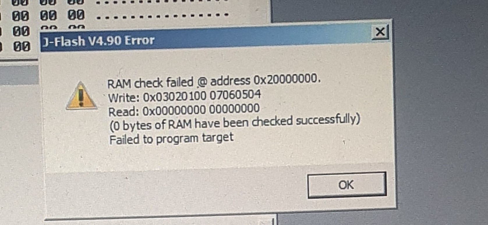
I am trying to flash the firmware on an HDMI board using this J-link but I get the error
Failed to connect
cannot establish a connection to target
It would not let me do anything until i updated the firmware which it updated ok
The led blinks from green to red
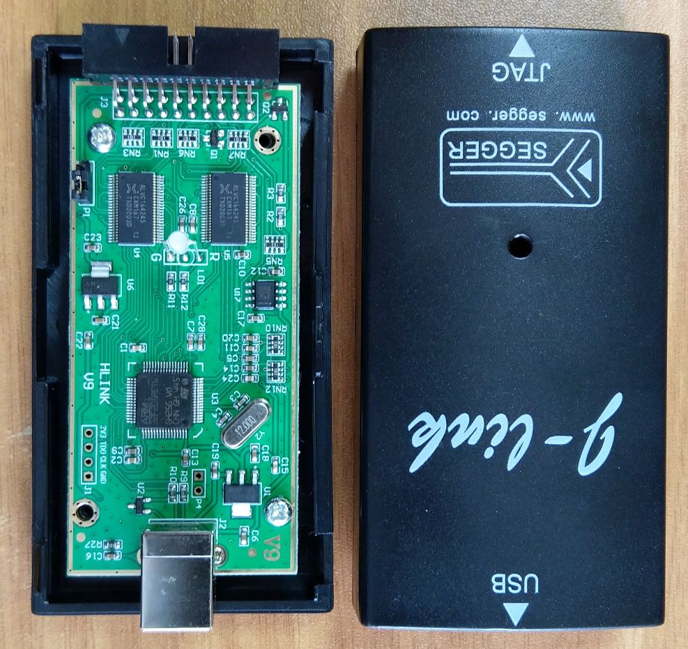
Attached are photos of the item
I do not know if I need to reflash the firmware or is it a setting
Please can someone help me
Thanks so much in advance
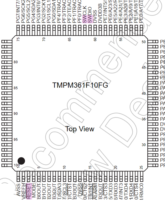
The Toshiba TMPM361F10FG, ARM Cortex-M3 based, isn’t even supported by PlatformIO, so I assume you’re not using PlatformIO?
The only advice I can give here is check the datasheet of the chip to see where the necessary SWD pins are. SWDIO and SWDCLK are pin number 61 and 62, RESET is number 3.
If you have all the wiring correctly regarding the SWD interface (and common GND) of course, it could just be that the JTAG/SWD interface has been disabled on the chip after programming, by burning an internal fuse. This is a very common countermeasure against people trying to dump the firmware off a commercial product for protection of intellectual property. See for example How the Apple AirTags were hacked - YouTube.
Also can someone explain what is jlink Target interface voltage “VIF”
It’s an analog input, intended use is measuring the target power supply voltage. It does not provide power for the target, just measures it.
The J-Link board on the picture is definitely a clone, and Segger actively defends against clones. Considering the low price of the jlink edu mini, what is the point for a clone?
However, if the Segger driver refuses a clone, it writes something like “Faulty device”, and your error message is different. So it’s possible that the reson is not the clone, but faulty wiring, missing target power, or incorrect settings.
Did you test it using the Segger JFlash Lite program for erasing or flashing the target?
What happens, if you test the Jlink adapter using the Jlink Commander or Jlink Configurator?
My edu mini’s response:
SEGGER J-Link Commander V7. 0a (Compiled Apr 16 2021 15:34:05)
DLL version V7.00a, compiled Apr 16 2021 15:32:47
Connecting to J-Link via USB…O.K.
Firmware: J-Link EDU Mini V1 compiled Feb 18 2021 11:25:23
Hardware version: V1.00
S/N: 801026507
License(s): FlashBP, GDB
VTref=3.293V
Type “connect” to establish a target connection, ‘?’ for help
J-Link>
The response of my Jlink edu (similar box to your clone):
SEGGER J-Link Commander V7. 0a (Compiled Apr 16 2021 15:34:05)
DLL version V7.00a, compiled Apr 16 2021 15:32:47
Try to check a different chip to decide whether the target, or the Jlink is the problem. Do you have a different chip, for example a BluePill (STM32F103C8T6) board?
HI
I am a first time user of using J-link
I know that I have been sold a J-link clone but have been told it works and read reviews from others that it works
I know the J-link edu is cheap but the edu version doesnt support the chip that i need to program
I have connected it correctly, I think
I am using SWD mode
I want to program a new TMPM361F10FG but i keep getting an error that I have uploaded
I don’t have other development boards to try My J-link clone on but I have a J-link V8 that is also a clone so what I thought is use My v9 J-link to read the J-link V8 firmware
Still get the same error
What am i doing wrong
Please can someone confirm how to wire this
I will really appreciate the help from everyone here
Thanks
did not connect reset
What I also tried is moving the jumper on the J-link v9 to output 3.3v on pin 2, vout
then I connected this pin to the vtref pin the j-link v8
but did not work
According to this link
It says VoUT is a 33V voltage output pin.
The user can remove the short-circuit cap inside the device and turn off the 3.3V output.
VTREF is the internal voltage reference, this pin must be connected to the vcC of McU
so does this mean the vtref pin goes to the vtref pin on the other j-link
i dont have schematics
Can you tell me how you would read the firmware on another jlink using a Jlink v9
please
how would i read this
if i know how you would do it then i can copy it
You are more experienced