Hi,
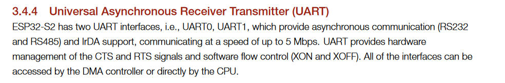
I have been looking for two days on forums at potential interaction between USB CDC and UART0 on an ESP32-S2. All I could find indicate that once USB_CDC_ON_BOOT is enabled the Serial Monitor is using CDC instead of the UART0 and UART0 is available for other use.
I must have missed something - any clue about what I could be doing wrong?
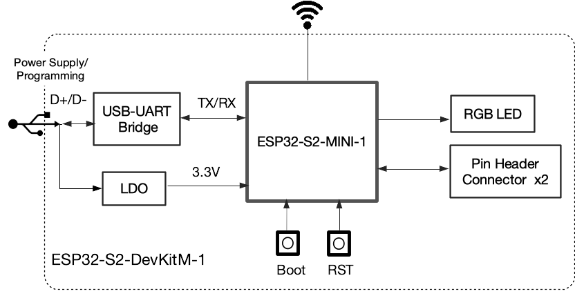
I am using an ESP32-S2-DevKitM-1 to validate some code before moving to a custom board with ESP32-S2-SOLO module.
USB CDC: serial monitor (USB_CDC_ON_BOOT = 1) with monitor speed = 115200
UART0: RS485 / Modbus Slave with speed = 19200
My issue is: When I start the Modbus slave communication stack then the monitor starts displaying garbage (it seems to be a problem of communication speed as all is fine if Monitor and Modbus slave are both set at the same speed).
platformio.ini
[env]
platform = espressif32
framework = arduino
build_flags =
   -DARDUINO_USB_CDC_ON_BOOT=1
   -DCONFIG_ARDUHAL_LOG_COLORS=1
   -DCORE_DEBUG_LEVEL=5

monitor_speed = 115200
monitor_filters = direct, esp32_exception_decoder
board_build.partitions = partitions.csv

[env:ESP32-S2-DevKitM-1]
board = esp32-s2-saola-1
Modbus slave setup:
#define GPIO_MB_SLAVE_TX    GPIO_NUM_43
#define GPIO_MB_SLAVE_RX    GPIO_NUM_44
#define GPIO_MB_485_SHDN    GPIO_NUM_15             // GPIO to shutdown RS485 (drive high for normal operation)
#define MB_SLAVE_UART       UART_NUM_0
#define MB_SLAVE_ADDR       1
#define MB_SLAVE_SPEED      19200
//#define MB_SLAVE_SPEED      115200
The code to setup the Modbus slave:
 esp_err_t mbSlaveSetup()
{
  log_v("Setup RS485 port and Modbus slave driver");
  pinMode(GPIO_MB_485_SHDN, OUTPUT);
  digitalWrite(GPIO_MB_485_SHDN, HIGH);

  esp_err_t err = ESP_OK;
  mb_slave_setup.mode = MB_MODE_RTU;
  mb_slave_setup.slave_addr = MB_SLAVE_ADDR;
  mb_slave_setup.port = MB_SLAVE_UART;
  mb_slave_setup.baudrate = MB_SLAVE_SPEED;
  mb_slave_setup.parity = MB_PARITY_NONE;
  reg_area.type = MB_PARAM_HOLDING;
  reg_area.address = ®
  reg_area.start_offset = 0;
  reg_area.size = REG_NUM * 2;

  log_v("Initialize Modbus slave controller");
  err = mbc_slave_init(MB_PORT_SERIAL_SLAVE, &mb_slave_handler);
  if (err != ESP_OK) {
    log_e("Error initializing the serial port for Modbus: %i", err);
    return err;
  }

  log_v("setup Modbus slave");
  err = mbc_slave_setup((void*)&mb_slave_setup);
  if (err != ESP_OK) {
    log_e("Error Modbus slave setup: %i", err);
    return err;
  }

  log_v("Set Modbus slave registers structure");
  err = mbc_slave_set_descriptor(reg_area);
  if (err != ESP_OK) {
    log_e("Error setting Modbus slave registers structure: %i", err);
    return err;
  }

  log_v("Initialize Modbus communication stack");
  delay(100);
  err = mbc_slave_start();
  if (err != ESP_OK) {
    log_e("Error starting Modbus communication stack: %i", err);
    return err;
  }

  log_v("Set Modbus / RS485 UART pins - UART: %i  /  TX: %i  /  RX: %i", MB_SLAVE_UART, GPIO_MB_SLAVE_TX, GPIO_MB_SLAVE_RX);
  err = uart_set_pin(MB_SLAVE_UART, GPIO_MB_SLAVE_TX, GPIO_MB_SLAVE_RX, -1, -1);
  if (err != ESP_OK) {
    log_e("Error setting Modbus / RS485 UART pins: %i", err);
    return err;
  }

  log_v("Set RS485 UART mode");
  delay(100);
  err = uart_set_mode(MB_SLAVE_UART, UART_MODE_RS485_HALF_DUPLEX);
  if (err != ESP_OK) {
    log_e("Error setting Modbus UART mode: %i", err);
    return err;
  }
  return ESP_OK;
}
Output:
[  2075][V][mb_slave.cpp:11] mbSlaveSetup(): Setup RS485 port and Modbus slave driver
[  2076][V][mb_slave.cpp:26] mbSlaveSetup(): Initialize Modbus slave controller
[  2081][V][mb_slave.cpp:33] mbSlaveSetup(): setup Modbus slave
[  2087][V][mb_slave.cpp:40] mbSlaveSetup(): Set Modbus slave registers structure
[  2096][V][mb_slave.cpp:47] mbSlaveSetup(): Initialize Modbus communication stack
�������������������������������������������������������������������������
if I set the MB_SLAVE_SPEED = 115200 the output is fine:
[  2074][V][mb_slave.cpp:11] mbSlaveSetup(): Setup RS485 port and Modbus slave driver
[  2075][V][mb_slave.cpp:26] mbSlaveSetup(): Initialize Modbus slave controller
[  2080][V][mb_slave.cpp:33] mbSlaveSetup(): setup Modbus slave
[  2086][V][mb_slave.cpp:40] mbSlaveSetup(): Set Modbus slave registers structure
[  2094][V][mb_slave.cpp:47] mbSlaveSetup(): Initialize Modbus communication stack
[  2203][V][mb_slave.cpp:55] mbSlaveSetup(): Set Modbus / RS485 UART pins - UART: 0  /  TX: 43  /  RX: 44
[  2203][V][mb_slave.cpp:62] mbSlaveSetup(): Set RS485 UART mode