Does it work for you with Eclipse?
See my comment here
Does it work for you now?
Hi ivan!
Please excuse my late response… It worked for me with Eclipse and after your fix it does work with PIO as well! Didn’t have to update my openOCD release as mine is not that dated…
Thanks a lot for your support!
1 Like
Doesn’t work for me. Breakpoints work only for the IDF code part. Arduino’s are skipped.
What is your OS? Debugging tool? Could you provide a screenshot of errors from Debug Console?
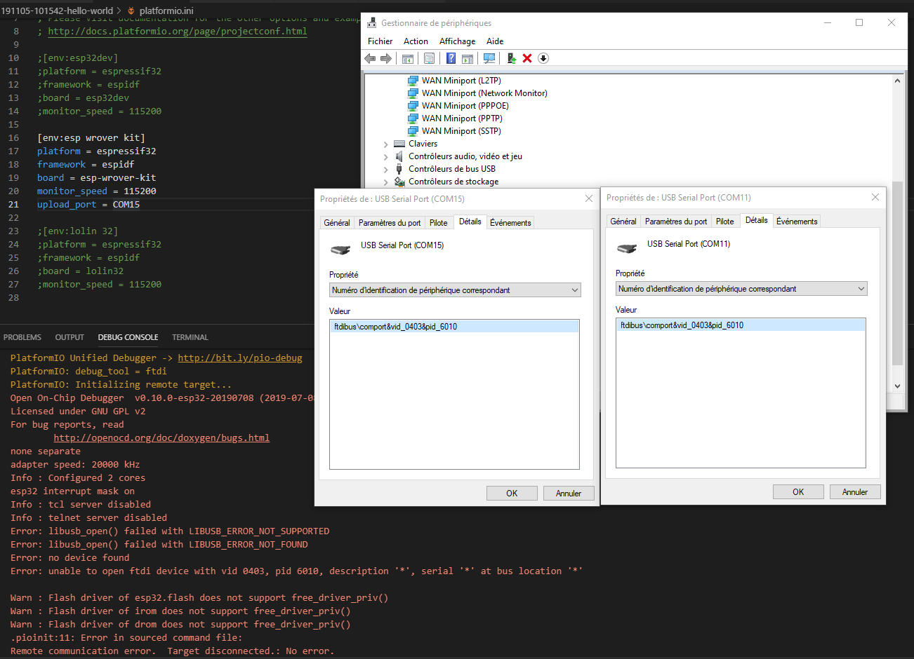
MacOS Mojave. WROVER FTDI. There is no error in debug console it just never halts at the breakpoint. Below is a screenshot of what happens if I reset breakpoint while running in loop.
Could you remove all breakpoints and start debugging again? Would be good to reconnect boards from USB. Does it stop at app_main?
It does stop at app_main. That’s the IDF part that works as I’d mentioned previously. Also breakpoints within IDF’s main.cpp work fine.
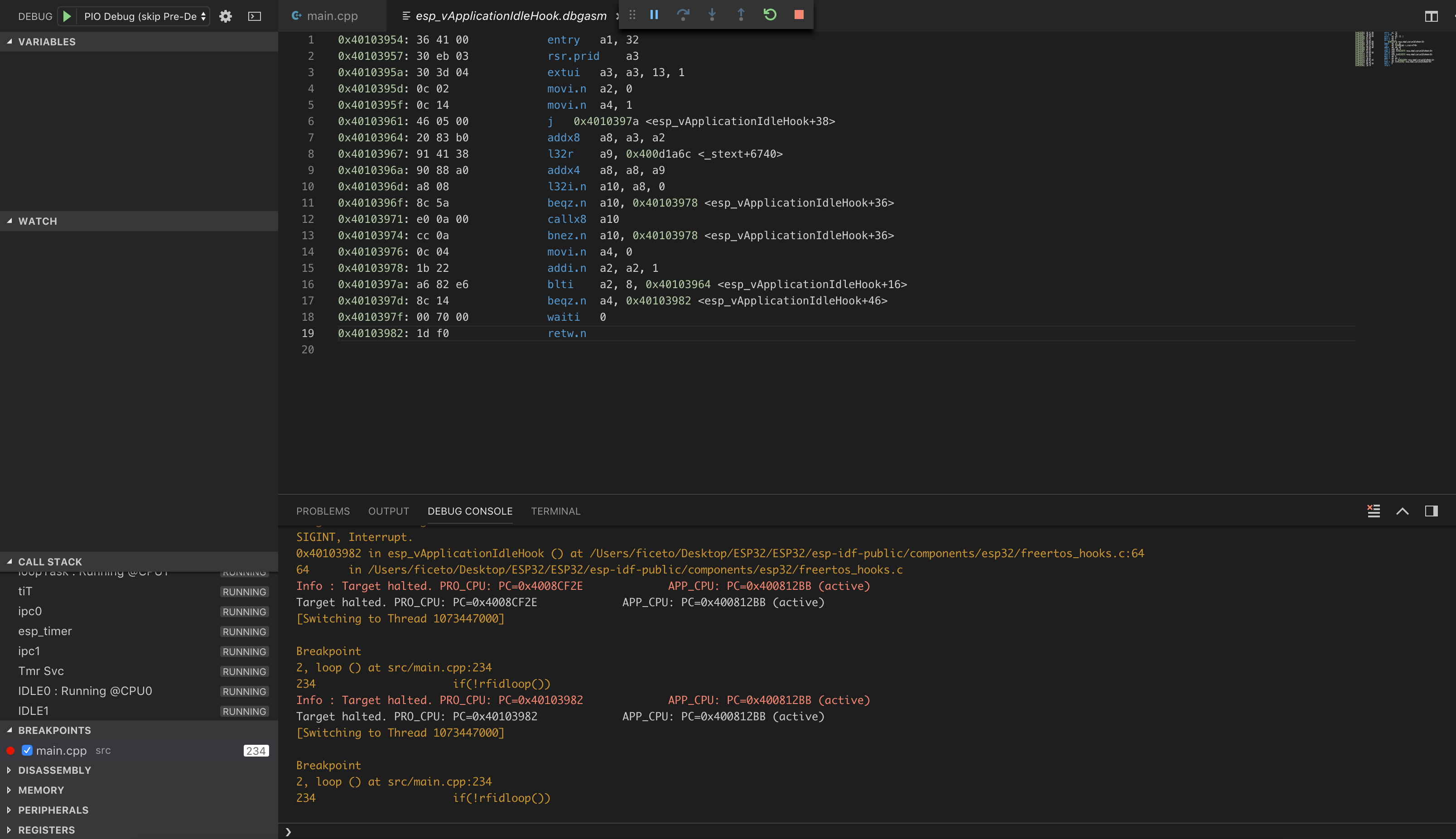
Also this is how a backtrace is handled:
Temporary breakpoint
1, app_main () at …/.platformio/packages/framework-arduinoespressif32@src-537c58760dafe7fcc8a1d9bbcf00b6f6/cores/esp32/main.cpp:22
22 {
Info : Target halted. PRO_CPU: PC=0x40103AAE APP_CPU: PC=0x400014FD (active)
Target halted. PRO_CPU: PC=0x40103AAE APP_CPU: PC=0x400014FD (active)
[New Thread 1073447000]
[New Thread 1073411240]
[New Thread 1073457028]
[New Thread 1073529700]
[New Thread 1073429100]
[New Thread 1073434048]
[New Thread 1073438628]
Program received signal
SIGTRAP, Trace/breakpoint trap.
[Switching to Thread 1073447000]
0x400014fd in ?? ()
- Please check that you use the latest PlatformIO Core and all packages are updated (you can update them using Left Sidebar > PlatformIO > Updates Packages)
- It seems that you use staging version of Arduino framework. Please switch back to stable dev/platform. Just for test.
- Remove all breakpoint.
- Start debugging session and set breakpoint when a session is established and you are at app_main.
- Press "Continue.
P.S: What is your board and debugging adapter?
See my log. I’ve just tried it and it works for me.
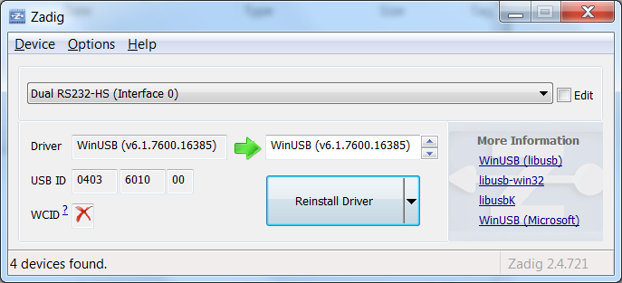
This seemed to work perfectly until step 7 where I’m supposed to use Zadig to replace the Dual RS232-HS (Interface 0) with WinUSB
I can’t seem to get the WinUSB driver installed and working. I got to “USB Serial Converter A” and “…B” in the USB controllers list, then ran Zadig on “Dual RS232-HS (Interface 0)” but it hung. Waited 10 minutes “(Not responding)”.
I restarted the PC, tried it again, and it said it worked. Unplugged, plugged in, and now I only have “USB Serial Converter A” (as expected) but no com port. Re-installing the driver via Zadig appears to work, but nothing shows up again under com ports. “Dual RS232-HS (Interface 0)” is now listed under “USB devices” and no ports.
Any ideas? or where else can I ask?
After installing the WinUSB driver on USB Serial Converter A channel, You should have “Dual RS232-HS” , “USB Serial Converter B” and “Com Port x” on device manager:
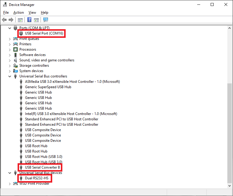
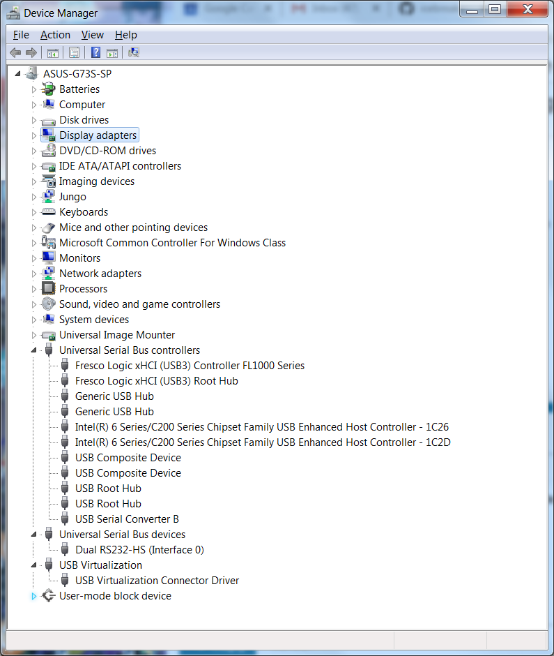
Um… yes… I’m fully aware of what I should have. What I instead have is what I described above. Which is why I’m asking for help. If a screen shot helps, this is what I’m seeing.
And here is what zadig looks like. And it DOES report that it succeeded.
 .
.
I don’t see the com port detected on your device manager.
Right click on “USB Serial Converter B”, go to “Advanced” tab and select “Load VCP”:
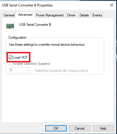
Then, the Com Port will be detected on device manager.
Check “Set the drivers” section from this tutorial: GitHub - botofancalin/Esp32_debug_template: A template project for debugginf esp-idf projects on VsCode
I explained there step by step how to set up the drivers.
I tried following the Get started with Arduino and ESP32-DevKitC: debugging and unit testing guide here:
https://docs.platformio.org/en/latest/tutorials/espressif32/arduino_debugging_unit_testing.html#id5
I ran into a problem starting the debugger getting the following error code. I reconfigured drivers as stated in this post. I’ve searched around and tried others’ fixes without success. Any ideas? I am using the esp32 devkitc v4 and ARM-USB-OCD-H as shown in the tutorial. Using Arduino framework
Reading symbols from >c:\Users\zesteron\platformio_projects_selfmade\trial_esp32.pio\build\esp32dev\firmware.elf…
done.
PlatformIO Unified Debugger → Redirecting...
PlatformIO: debug_tool = olimex-arm-usb-ocd-h
PlatformIO: Initializing remote target…
Open On-Chip Debugger v0.10.0-esp32-20190708 (2019-07-08-11:04)
Licensed under GNU GPL v2
For bug reports, read
//OpenOCD: Bug Reporting
adapter speed: 2000 kHz
Info : Configured 2 cores
esp32 interrupt mask on
Info : tcl server disabled
Info : telnet server disabled
Info : clock speed 2000 kHz
Error: JTAG scan chain interrogation failed: all zeroes
Error: Check JTAG interface, timings, target power, etc.
Error: Trying to use configured scan chain anyway…
Error: esp32.cpu0: IR capture error; saw 0x00 not 0x01
Warn : Bypassing JTAG setup events due to errors
Info : accepting ‘gdb’ connection from pipe
Error: No symbols for FreeRTOS
Error: Target not examined yet
Error: Target not halted
Error: auto_probe failed
Error: Connect failed. Consider setting up a gdb-attach event for the target to prepare target for GDB connect, or use ‘gdb_memory_map disable’.
Error: attempted ‘gdb’ connection rejected
Error: error during select: Unknown error
Warn : Flash driver of esp32.flash does not support free_driver_priv()
Warn : Flash driver of irom does not support free_driver_priv()
Warn : Flash driver of drom does not support free_driver_priv()
.pioinit:11: Error in sourced command file:
Remote communication error. Target disconnected.: No error.
The message
Error: JTAG scan chain interrogation failed: all zeroes
indicates that the wiring between the ESP32-DevKitC V4 and ARM-USB-OCD-H is likely incorrect or not properly working. The drivers are okay as the log shows that OpenOCD (on your computer) can talk to the ARM-USB-OCD-H.
Can you double check the wiring and make sure it like so:
| ESP32-DevKitC V4 | ARM-USB-OCD-H |
|---|---|
| GPIO12 — TDI | 5 — TDI |
| GPIO15 — TDO | 13 — TDO |
| GPIO13 — TCK | 9 — TCK |
| GPIO14 — TMS | 7 — TMS |
| GND | 4 — GND |
And make sure the ARM-USB-OCD-H pinout is not mirrored. As a reference: the red wire in the ribbon cable is pin 1.
The above wiring assumes the ESP32 board is powered via USB.
2 Likes
Thank you! It seems I was looking at it mirrored (looking into the pin holes).
And to power the ESP32-DevKitC V4 from the ARM-USB-OCD-H and not via USB, I would connect to 5V in of the esp32 to go through its regulator, not to the 3.3V pin as the tutorial states that I linked, right? Since the ARM-USB-OCD-H supplies 5V.
1 Like
I’m unsure about VCC as I have never used ARM-USB-OCD-H. According to the documentation, it seems to be clever and first measures the voltage at the pin and if it iss zero it will provide power (5V). So yes, connect it to the 5V pin and see if it works.
1 Like