I am new to PlatformIO and microcontroller programming as a whole so please bear with me. I recently started my first project and when it came time to debug I got the following in my debug console:
undefinedC:\Users\Mark\.platformio\packages\toolchain-riscv32-esp\bin\riscv32-esp-elf-gdb.exe: warning: Couldn't determine a path for the index cache directory.
Reading symbols from c:\Users\Mark\Documents\Source\PlatformIO\Test Debug\.pio\build\lolin_c3_mini\firmware.elf...
PlatformIO Unified Debugger -> https://bit.ly/pio-debug
PlatformIO: debug_tool = cmsis-dap
PlatformIO: Initializing remote target...
Open On-Chip Debugger  v0.11.0-esp32-20220706 (2022-07-06-15:48)
Licensed under GNU GPL v2
For bug reports, read
	http://openocd.org/doc/doxygen/bugs.html
adapter speed: 5000 kHz

Info : tcl server disabled
Info : telnet server disabled
Error: unable to find a matching CMSIS-DAP device

Error: Unsupported xlen: -1
Error: Unknown target arch!
.pioinit:11: Error in sourced command file:
Remote communication error.  Target disconnected.: Success.
So after doing some reading…I removed all Serial references in my code and getting the same error, I started a new project with nothing in it - just an empty setup{} and loop{}…and got the same error. Was wondering if someone could point me in the right direction. I also get the following VS Code message:
"Failed to launch GDB: .pioinit:11: Error in sourced command file: Remote communication error. Target disconnected.: Success. {from interpreter-exec console “source .pioinit”)
Any help is really appreciated
The default configuration expects you to have CMSIS-DAP type external debugger attached to your hardware. Which you likely not have.
However, the ESP32-C3 also has a built-in JTAG debugger, same as the ESP32-S3
https://docs.espressif.com/projects/esp-idf/en/v5.0/esp32c3/api-guides/jtag-debugging/configure-builtin-jtag.html
But it depends on your development board whether the native USB connections of your ESP32-C3 are available on a USB port, or whether the USB port on your dev board just go to a generic USB-to-UART adapter to talk to the board. If your board has two USB ports, likely one of them is the native ESP32-C3 USB port.
If you have that, you can set
upload_protocol = esp-builtin
debug_tool = esp-builtin
in the platformio.ini to try and connect to that builtin debugger, also see issue.
1 Like
Thanks max! Guilty as charged…I didn’t know I needed an external debug tool for my board. My board only has a single usb connection. It is the lolin esp32-C3 pico.
The docs you referenced say:
" Only an USB cable connected to the D+/D- pins is necessary. The necessary connections are shown in the following section.
ESP32-C3 pins and USB signals
|GPIO18|D-|
|GPIO19|D+|
|5V|V_BUS|
|GND|Ground|
Please verify that the ESP32-C3 pins used for USB communication are not connected to some other HW that may disturb the JTAG operation."
So does that mean if I use a breakout cable to these pins and connect them via usb to my pc, then in theory it should work? (assuming I look into some of the driver concerns). Also, when I do this should I have my boards usb connected as well as the breakout?
Thanks…you really helped out!
Fish
But, the USB connection exactly is the built-in ESP32-C3 USB port. There’s no USB-to-UART converter on the board per https://www.wemos.cc/en/latest/_static/files/sch_c3_pico_v1.0.0.pdf
So no need to buy a debugging probe.
I added the 2 lines above to my .ini file and now it looks like it recognizes the on-chip debugger but I am still getting errors:
undefinedC:\Users\Mark\.platformio\packages\toolchain-riscv32-esp\bin\riscv32-esp-elf-gdb.exe: warning: Couldn't determine a path for the index cache directory.
Reading symbols from c:\Users\Mark\Documents\Source\PlatformIO\Test Debug\.pio\build\lolin_c3_mini\firmware.elf...
PlatformIO Unified Debugger -> https://bit.ly/pio-debug
PlatformIO: debug_tool = esp-builtin
PlatformIO: Initializing remote target...
Open On-Chip Debugger  v0.11.0-esp32-20220706 (2022-07-06-15:48)
Licensed under GNU GPL v2
For bug reports, read
	http://openocd.org/doc/doxygen/bugs.html
Info : only one transport option; autoselect 'jtag'
Info : esp_usb_jtag: VID set to 0x303a and PID to 0x1001
Info : esp_usb_jtag: capabilities descriptor set to 0x2000
adapter speed: 40000 kHz

Warn : Transport "jtag" was already selected
adapter speed: 5000 kHz

Info : tcl server disabled
Info : telnet server disabled
Error: libusb_open() failed with LIBUSB_ERROR_NOT_FOUND
Error: esp_usb_jtag: could not find or open device!

Error: Unsupported xlen: -1
Error: Unknown target arch!
.pioinit:11: Error in sourced command file:
Remote communication error.  Target disconnected.: Success.
I’ve seen a lot of people have to monkey around with their COM ports when they use JTAG devices. I’m wondering if it is something like that?
So I found a bunch of info about running the usb drivers from Zadig…is that it?
The documentation says you need to have WinUSB drivers loaded for the JTAG interface here.
You can do that with their linked drivers or by using zadig.akeo.ie/ (List All Devices should be turned on).
For the USB JTAG device to show up, you might have to start the the chip in DFU bootloader mode. Which per documentation you can with GPIO9. The board has two buttons exactly for that: Hold down the “9” button, press and release RESET while the “9” button is still being held, then release the “9” button. It should restart the MCU in bootloader mode.
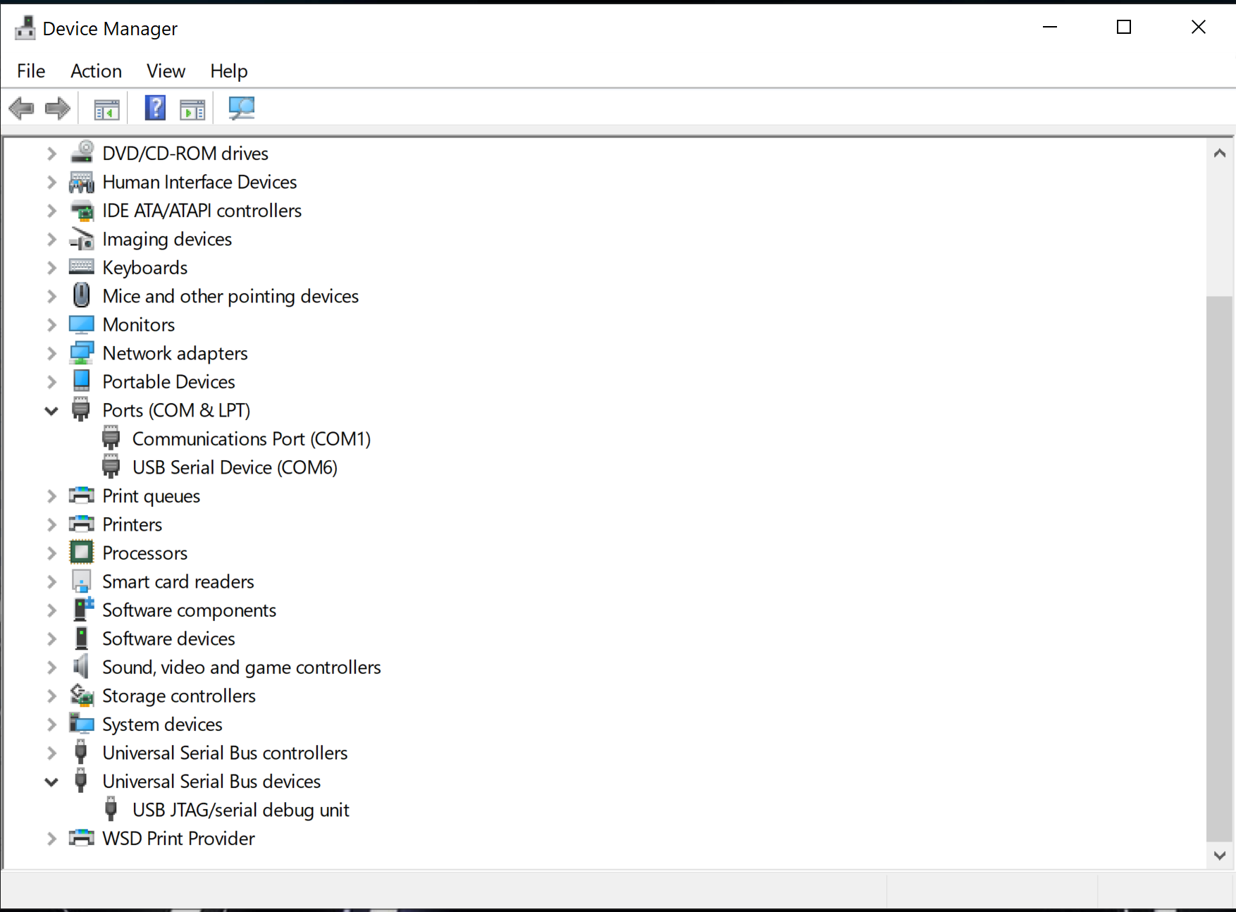
The device is showing up in Device manager as USB JTAG/serial debug unit
I think we are getting close.
I tried entering bootloader mode, but it didn’t make a difference…same errors/
what is this portion of the debug messages?
undefinedC:\Users\Mark.platformio\packages\toolchain-riscv32-esp\bin\riscv32-esp-elf-gdb.exe: warning: Couldn’t determine a path for the index cache directory.
That’s an ignorable warning, it doesn’t affect anything critical.
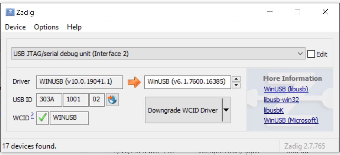
What does Zadig say about the driver loaded onto the USB JTAG/serial debug unit? WinUSB?
yes it is showing as WINUSB (v10.0.1904.1)
should I try changing to libusb-win32 (v1.2.6.0) driver?
Some of the other videos I have seen when using different JTAG devices, the COM port of the debug device is different that that of the board under test. Also, I had another esp32 that when it went into bootloader mode, it changed its COM port. This almost looks like the JTAG device is using the same COM port (COM6).
Error: libusb_open() failed with LIBUSB_ERROR_NOT_FOUND
Error: esp_usb_jtag: could not find or open device!
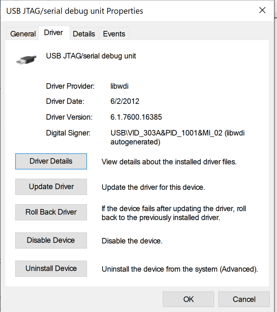
SUCCESS!! O.K. Max, I found some info. Apparently, the Espressif installer was installing the latest Microsoft Windows Drivers. You don’t want those…you want the ones signed by Espressif or the one that shows Driver Provider: libwdi as shjown here:
This is the default that can be installed by Zadig.
Thank you soo much for your help, Max!
Fish
2 Likes
Great info and great debugging.
@fishbone My custom ESP32-C3 board isn’t showing up in my device manager. Could you share the schematic for your board? Or, if you could take a look at my schematic, the board contains only the ESP-C3 and the necessary components that should make it work. It’s a very basic board. I use the built-in USB/JTAG converter.
I don’t know if the two different boot modes make a difference if the COM port shows up in the device manager.
Thanks.
Oliver. Take a look at my schematic here:
https://www.wemos.cc/en/latest/c3/c3_pico.html
There should be a link to the schematic. When you say your board does not show up in your device manager…I assume PIO cannot see it and you cannot upload sketches?
Mark
Thank you!
I have not checked with PIO yet because I expect my board to show up in the device manager, so I know I have a connection before I move on from the hardware part. However, when I compared your schematic to mine, I have not grounded EP; it is simply floating. From what I can recall it wasn’t mandatory to connect EP, coult that be the case maybe?
In an earlier design I had built I did have EP grounded but never soldered the pad underneath, this board did not show up in the device manager either.
I’ll attach my schematic here of the current design.
Schematic
On the Espressif datasheet for the C3, pin 33 (EP) is defined as Ground…so I would definitely ground it. Not sure if that is your problem, but it is something you should do.
This was my problem! I don’t get how I missed soldering the pad underneath; it works now!
I tried uploading a simple print with “Hello world” in a loop, and it uploaded successfully. However, it doesn’t print anything on the serial monitor. If I unplug and plug the USB back in it, then it prints out “waiting to download” and some other info such as “boot: 0x7” which I’m guessing is the booting mode set by the strapping pins.
I don’t think I quite understand the two different booting modes and what to use. Currently, GPIO2 is HIGH, GPIO8 is HIGH and GPIO9 is LOW.