Hello everyone,
I want to debug and program an STM32F446RE using the C232HM-EDHSL-0. I’ve already read several discussions in the forum, but I can’t quite figure out why it’s not working.
I must also say that I am new to this topic and I am very glad about any help.
# interface/ftdi/c232hm.cfg

#

# FTDI USB Hi-Speed to MPSSE Cable

#

# http://www.ftdichip.com/Products/Cables/USBMPSSE.htm

#

# C232HM-DDHSL-0 and C232HM-EDSL-0 provide 3.3V and 5V on pin 1 (Red),

# respectively.

#

# Adapter: http://www.ftdichip.com/Support/Documents/DataSheets/Cables/DS_C232HM_MPSSE_CABLE.PDF

# Chip: http://www.ftdichip.com/Support/Documents/DataSheets/ICs/DS_FT232H.pdf

# See pinout/colors at end of this file.

#

# Tech notes:

# http://www.ftdichip.com/Support/Documents/AppNotes/AN_135_MPSSE_Basics.pdf

# http://www.ftdichip.com/Support/Documents/AppNotes/AN_129_FTDI_Hi_Speed_USB_To_JTAG_Example.pdf

#

# This was tested with the 3.3V version adapter (FTDI part number C232HM-DDHSL-0). It should also

# work with the 5V version (C232HM-EDHSL-0), but this has not been tested.

#

# In testing, with adapter_khz at 26000 or 30000 MHz, read speed topped out around 2.2 KiB/s.

# This allowed dumping a 4MB flash chip in about 30 minutes, for example.

interface ftdi

#ftdi_device_desc "C232HM-DDHSL-0"

#ftdi_device_desc "C232HM-EDHSL-0"

# Common PID for FT232H

ftdi_vid_pid 0x0403 0x6014

# Layout

# High data 0xff makes ACBUS (which includes LED on ACBUS6) initially high (off).

# Low data byte 0xf8 makes TRST (AD4) and SRST (AD5) initially high (unasserted).

# High direction 0x40 makes only ACBUS6 output (connected to red LED)

# Low direction 0xfb makes GPIOL0/1 output; used for T/SRST signals below. Only TDO is input (low).

ftdi_layout_init 0xfff8 0x40fb

# Optional Signals (Comment out ftdi_layout_signal line(s) below if board doesn't have T/SRST.)

# ---A*BUS-------CCCCCCCC|DDDDDDDD

# --------\______76543210|76543210

# nTRST 0x0010 = 00000000|00010000 = ADBUS4 (gray)

# nSRST 0x0020 = 00000000|00100000 = ADBUS5 (purple)

# LED 0x4000 = 01000000|00000000 = ACBUS6

ftdi_layout_signal nTRST -data 0x0010 -oe 0x0010

ftdi_layout_signal nSRST -data 0x0020 -oe 0x0020

ftdi_layout_signal LED -data 0x4000 -noe 0x4000

# LED toggle procedures

proc c232hm_LED_on {} {

ftdi_layout_signal LED -data 0x4000 -oe 0x4000

}

proc c232hm_LED_off {} {

ftdi_layout_signal LED -data 0x4000 -noe 0x4000

}

# C232HM FT232H JTAG

# Num Color Name Func

# 1 Red VCC N/A - Do not connect

# 2 Orange ADBUS0 TCK

# 3 Yellow ADBUS1 TDI

# 4 Green ADBUS2 TDO

# 5 Brown ADBUS3 TMS

# 6 Grey ADBUS4 (GPIOL0)/nTRST

# 7 Purple ADBUS5 (GPIOL1)/nSRST

# 8 White ADBUS6 (GPIOL2) - not used

# 9 Blue ADBUS7 (GPIOL3) - not used

# 10 Black GND Connect to ground

# end interface/ftdi/c232hm.cfg
With no error message and no wireup info between your FTDI and STM32 chip given, we can hardly help.
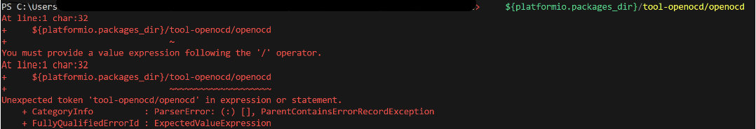
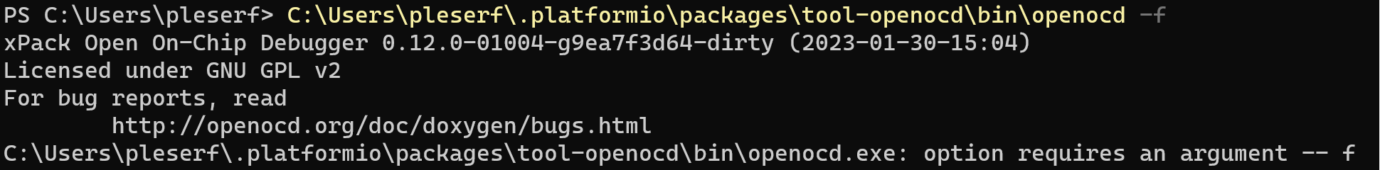
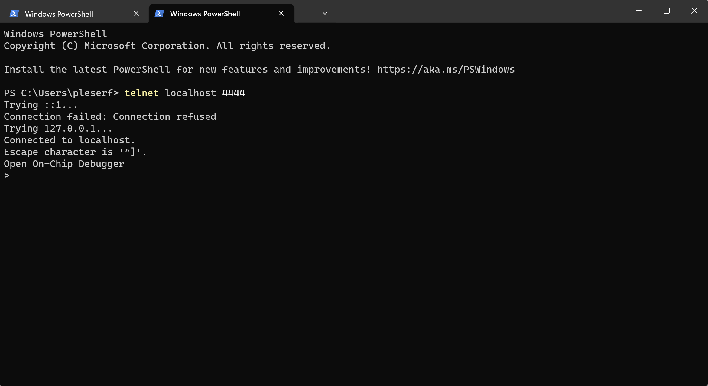
At the very start, you should make sure that OpenOCD can at least connect with the config you gave it. That is, open up a new terminal and manually execute
Thank you for the answer.
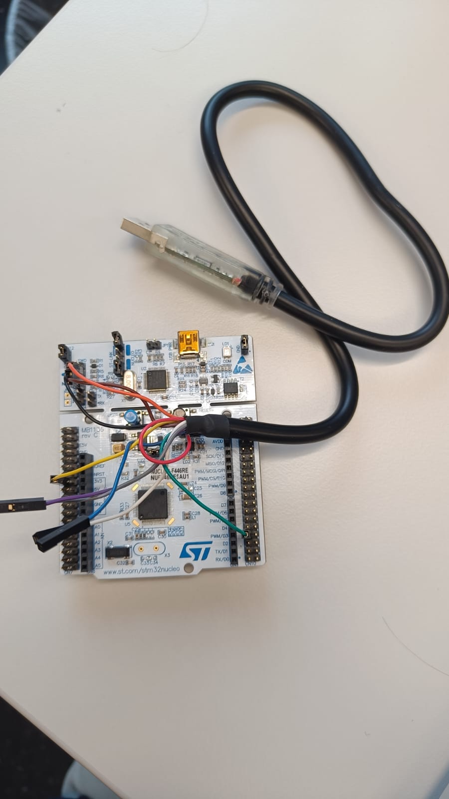
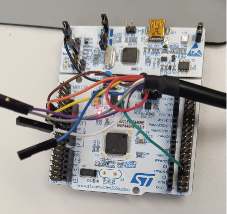
I want to use only the STM32F446RE microcontroller from the Nucleo board. The rest of the Nucleo board I have disconnected with the jumpers. Now I want to use the C232HM Cable with JTAG to program and debug the STM32F446RE to test how it works.
Okay when I read this I thought you already had created a custom config file for this.
In this case no, because standard OpenOCD already has the interface definition, so you should not have to add any file. The “interface” (your debug adapter) and the “target” (the microcontroller you’re connecting to) are two different config files. So your invocation should look something like this
Sorry for the confusion, and thanks for the additional information. I now have a problem with the JTAG connection. The microcontroller can do both SWD and JTAG, do I need to define that?
C:\Users\<user>\.platformio\packages\tool-openocd\bin\openocd.exe -s C:\Users\<user>\.platformio\packages\tool-openocd\openocd\scripts -f interface/ftdi/c232hm.cfg -c "transport select jtag" -f target/stm32f4x.cfg
xPack Open On-Chip Debugger 0.12.0-01004-g9ea7f3d64-dirty (2023-01-30-15:04)
Licensed under GNU GPL v2
For bug reports, read
        http://openocd.org/doc/doxygen/bugs.html
jtag
Info : Listening on port 6666 for tcl connections
Info : Listening on port 4444 for telnet connections
Info : clock speed 2000 kHz
Error: JTAG scan chain interrogation failed: all ones
Error: Check JTAG interface, timings, target power, etc.
Error: Trying to use configured scan chain anyway...
Error: stm32f4x.cpu: IR capture error; saw 0x0f not 0x01
Warn : Bypassing JTAG setup events due to errors
Error: Invalid ACK (7) in DAP response
Error: JTAG-DP STICKY ERROR
But you only have SWD lines (SWDIO, SWDCLK, NRST) hooked up?
If you hook the debugger up to the JTAG pins correctly, it should equivalently be able to connect via JTAG. JTAG is on by default. In fact, SWD is initiated by sending a JTAG-to-SWD transition sequence on what are initially JTAG lines.
The JTAG pins can be found in the microcontroller’s datasheet. A good reference for the nucleo board is mbedos.
Ah, my mistake.
I have reconnected it. Now the connection looks good.
Thanks a lot
C:\Users\<user>\.platformio\packages\tool-openocd\bin\openocd.exe -s C:\Users\<user>\.platformio\packages\tool-openocd\openocd\scripts -f interface/ftdi/c232hm.cfg -c "transport select jtag" -f target/stm32f4x.cfg
xPack Open On-Chip Debugger 0.12.0-01004-g9ea7f3d64-dirty (2023-01-30-15:04)
Licensed under GNU GPL v2
For bug reports, read
        http://openocd.org/doc/doxygen/bugs.html
jtag
Info : Listening on port 6666 for tcl connections
Info : Listening on port 4444 for telnet connections
Info : clock speed 2000 kHz
Info : JTAG tap: stm32f4x.cpu tap/device found: 0x4ba00477 (mfg: 0x23b (ARM Ltd), part: 0xba00, ver: 0x4)
Info : JTAG tap: stm32f4x.bs tap/device found: 0x06421041 (mfg: 0x020 (STMicroelectronics), part: 0x6421, ver: 0x0)
Info : [stm32f4x.cpu] Cortex-M4 r0p1 processor detected
Info : [stm32f4x.cpu] target has 6 breakpoints, 4 watchpoints
Info : starting gdb server for stm32f4x.cpu on 3333
Info : Listening on port 3333 for gdb connections
Info : [stm32f4x.cpu] external reset detected
Great, now you can set debug_tool = custom and the debug_server your found correct OpenOCD invocation, as documented in debug_server — PlatformIO latest documentation and that should enable the debugging sidebar → “PIO Debug” task to work.
Serial is not the right upload protocol if you want to upload via your FTDI. If you want the “Upload” button to work properly too with your custom debug adapter, you’ll have to teach PlatformIO the right upload command, which again involves OpenOCD. See upload_command — PlatformIO latest documentation. Something along the lines of
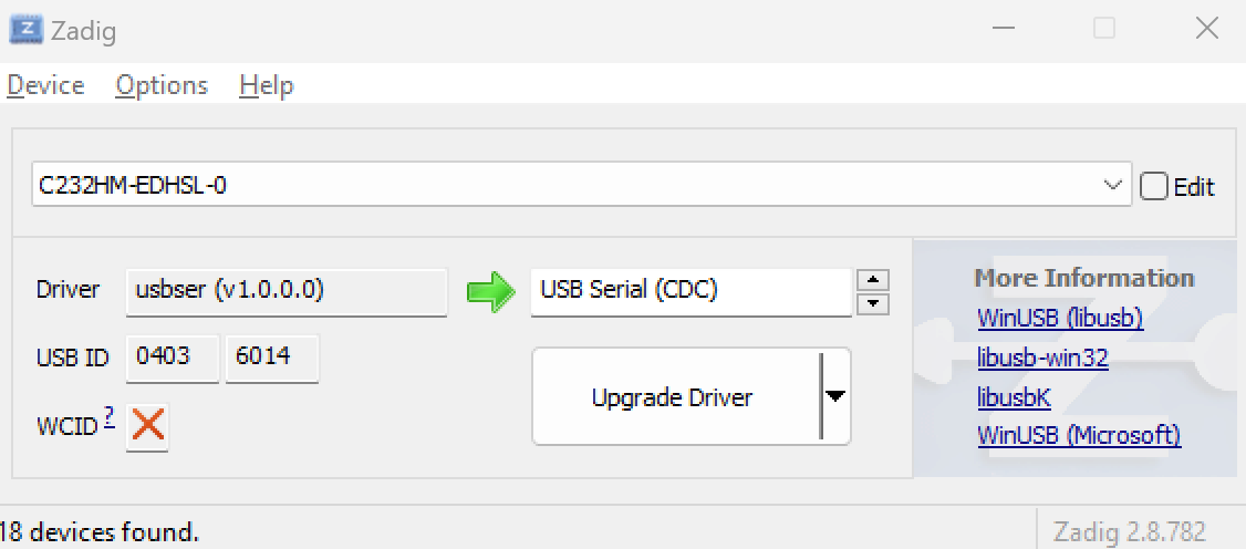
No, the FTDI 232H chip in the C232 has one channel, that can be either JTAG or UART. So you should undo that change by uninstalling that driver in the Windows device manager or use change it back in Zadig to what it was before (WinUSB probably), since changing that away to USB-CDC has destroyed OpenOCD’s capability to communicate with the adapter properly.
Execute the project task → Advanced → “Verbose Upload” to see the exact uplaod invocation, maybe some error will be apparent there in the paths or command.