What I’m trying here should not be hard - I must be missing something. Let me try to give as much info as possible without going overboard and get you all bored
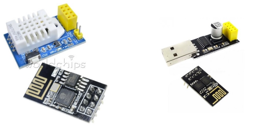
I bought 3 of these sets on the left in the image below- note they came with esp01S boards.
Then I also got the kit on the right so I can get them programmed & running (included came an ESP-01)
Software is no problem for me - been a developer for 25yrs (but not an expert on any level when it comes to hardware) so I had the coding done long before the units even got delivered. Managed to get it uploaded to the esp-01s modules, but code never executed. After some research I changed the flash mode setting to dout and the code ran - wifi works as well as serial monitor. But when I connect the esp01s to the dht22 unit and power up, it refuses to read the values from the sensor. After a lot of testing I decided to try with the esp01 from the usb connecter “kit”, and it worked perfectly - everything.
The only possibility I can think of is that i know the dht’s data pin is on pin 2 of the esp. I also know that when I ran the blink test on the ESP01S modules I had to specify the built in led is on pin 2 - with the esp01 specifying that was not required to get the blink working. Could this be the reason - led & dht on pin 2? Somehow I doubt it - why would a kit be sold with the dht22 and esp01s which only works with the esp01?
Either way, I have no idea what to try nor where to search online for answers anymore - any and all help will be very much appreciated.
You’re not using the built-in LED pin in parallel to the DHT22 code when the DHT22 data line is connected to the same GPIO pin as the built-in LED is right?
The LED might be the exact reason it isn’t working. If the LED sits on the data-line, and the DHT22 sensor’s data line is bidirectional (controlled by the ESP32 and DHT22 one after the other), it might be that when the DHT22 asserts a LOW on the data line that makes a current want to flow from the sensor’s data pin into the LED to light it up. the DHT22 data pin however surely doesn’t have the driver-strength to pump out the required milliamps to drive an LED, and so the system collapses. The only way you can really test that is by either cutting off the built-in LED from the ESP01-S or by explicitly adding one in the same way the ESP01-S does on a ESP-01 board and see if that suddenly makes things fail.
Not in my code no. I only used that with the blink test. I do however (and this is required regardless of board) when using the DHT22 specify its data pin to be pin 2 as that how the kit was built.
I understand the test you are referring to, but I just find it hard to believe that a kit being sold in their thousands will need any type of hw mods , not to mention this type of heavy mods.
Not sure if its worth mentioning (and maybe you knew this already), the ESP01s has only one built-in led (connected to pin 2) whereas the ESP01 (the one that does actually work) have 2 built-in leds.
I doubt that the issue is “driver” related. From my (still limited) understanding, the minor differences between the esp01 and esp01s does not extend to the way they “run your code”. Same platform, same processor. I want this fix to be as simple as just a code change, but that internal led on pin2 on the esp01s and the fact that this DHT22 kit also physically connects to that same pin2 is bugging me.
btw - with beegee’s dht22 lib, as per the adafruit, i had to set the dht pin to 2 in code.
Can you create a test where you use an ESP-01 and plug the ESP8266 USB adapter into your your PC, connect power (3.3V, GND) and UART between the two (for programming), then connect GPIO2, GND and 3.3V from the ESP8266 to the DHT22 sensor’s respective DATA, GND and VCC pins and see if that work normally? Then add an external LED on the dataline and see if it still works?
You can also ask your seller to provide an exact test sketch so that you can to prove or disprove the working state.
If two different respectable libraries are not working with your hardware, I start doubting that the fault is on the software side, otherwise a lot of people would be complaining that the libraries are faulty.
That link to fixing the Wemos D1 - extremely interesting reading which kinda confirms the suspicions - that wemos also had an led connected to the pin the dht22 also used as data pin. Another striking similarity I did not take notice of before nor mentioned, the built-in led on the esp01s does not act as a power on indicator - the only times i see it blinks/flashes is while new code is being uploaded - and that as I gather happened on the wemos too.
Also, in the case of that wemos, the original shield as it seems was designed to work with the older dht11 sensor and has been upgraded to the dht22 and that was when the issue appeared - same thing with the “shield” im using - was originally used for the dht11 sensor.
Im pretty sure changing the shield to use another data pin for the sensor will fix the issue, but alas I have no idea on what would b e the simplest way top do that…
Ok - while being completely flooded by responses on this question ( ) the following progress have been made:
After putting away my “fear” of changing hardware, I removed the connection on the circuit board of the DHT22 “shield” between GPIO2 of the ESP01S and reconnected it to GPIO1 (Tx). I did not opt for using GPIO0 as I think it will interfere with flash mode (could be wrong here, but I did try it and nothing worked). Using GPIO1 lead to some interesting and weird results. It now works, but VERY intermittently. The code is suppose to be “looping” every 5 minutes (simple delay statement delaying 5x60x1000 millisecs) but I keep on getting inconsistent readings. Below is the very simple text file recording every successful reading from the sensor.
Just a simple timestamp, the mac address from the esp01s and finally the temperature and humidity readings from the DHT22 on that esp01s. When I look at the same log file for the esp01 (the one that always worked) it looks like this:
11:17:22 AM -> A4:CF:12:D0:08:C8,24.70,43.80
11:22:23 AM -> A4:CF:12:D0:08:C8,24.80,44.80
11:27:23 AM -> A4:CF:12:D0:08:C8,24.90,47.70
11:32:41 AM -> A4:CF:12:D0:08:C8,25.50,49.00
11:37:31 AM -> A4:CF:12:D0:08:C8,25.40,44.00
The little knowledge I have tells me the issue has to be the fact that I used GPIO1 - Tx - and somehow that interferes (sometimes) with the wifi not connecting or something.
When looking at the “inconsistent readings”, it can be observed that the humidity is related to the temperature, i.e. lower humidity for higher temperature. This is how the relative humidity works.
Since the humidity is calculated on the sensor, it strongly indicates that the communication between MCU and sensor is working correctly, but the temperature is not measured correctly on the sensor.
It’s clearly an analog problem, not a digital one. If it was digital, the values would be far more random and temperature and humidity would not correlate.
Erm… Yeah I did not make this clear - the inconsistency has to do with WHEN the readings happen - the readings themselves are good.
The code is written to execute every 5 minutes with a simple delay statement. On the esp01 it executes as it should every 5 mins (see timestamps in example), not the case with the esp-01s - the example is the logs AS IS, in other words those were the only readings in that time period.
It would probably be helpful if you described in more detail and with technical terms:
What do you expect to happen?
What happens instead and how does it manifest itself?
So far, the only thing we know is: “it refuses to read the values from the sensor”. That’s how you would describe the behavior of a human being. But I doubt the ESP01 has its own will.
If it “refuses to read the values from the sensor”, it obviously does not output anything either. Why is that? Have you done any analysis on that?
It would probably also be helpful if you created a minimal and reproducible example and showed it here.
And how did you transmit the output? I guess you are not using the serial output as you are now using the TX pin for the communication with the sensor.
If you properly read my first post, you will have answers to every one of your question - as well as understand the out-of-context quote - the message I was trying to get across was that the ESP-01s did not read from the sensor but when I used the esp-01 that I had extra it worked perfectly as it should.
This is what I would like to accomplish using the “kit” as bought (in other words with the esp-01s boards):
(Power management I will look at down the line - need to get the basics going first - for now the batteries only lasts 24hrs, but thats ok for this testing - power works, issue is not there)
DHT22 sensor on a breakout board connected to an ESP01s + battery power supply. The sketch on the ESP executes every 5 minutes and gets a temperature and humidity reading from the DHT22. The reading is then sent to a local webserver on the network using simple http.
As already mentioned, the original code I wrote worked fine when I tested with an esp01. The ESP01s did not execute the code at all. When I tried to comment out all code that connects to or reads from the sensor (passing in test dummy values to the http “sender”), I could see the data got to the webserver. Moment I try to connect to DHT22 code fails completely.
This is when I started playing around with using a different GPIO pin for the DHT22 data connection. Tried the Tx pin (and changed code for new pin config), and now at this point it runs perfectly but only “sometimes”. This can best be explained when you look at the logs I posted before. The first set is how it is running now - timestamps shows it is not every 5 mins. The second set of logs was to show what it SHOULD be looking like - notice the timestamps and see the perfect 5 minute difference every time. This is weird since it seems to be working sometimes and then not.
I hope you can see the issues now, please advise if you need any more details.
The problem is somehow related to the DHT22. But wouldn’t it be possible that the sensor data can be successfully read by the MCU but fails when transmitting it to the server? After all, the server receives nothing at all. I would rather suspect that it receives a random value or a NaN value.
Do you have some kind of error handling in case the DHT22 communication fails?
If it is more of an electrical problem (e.g. DHT22 uses so much power that there isn’t sufficiently left for WiFi communication), it should be possible to test it with the DHT22 physically connected but using code without the DHT22 part.
Hello,
Did you finally get around the problem?
I bought the same type of equipment ESP01S+DHT22 on the same board, and fail to have it working with the code provided by the seller (he took it from the website of another seller).
I had an ESP 01, so I tried changing the ESP-01S by the 01, and it works fine (with my own code, and the code provided by the seller.
I got frustrated, and tried few thing. I have an USB connector to plug the ESP to the computer and upload code, or use the serial monitor.
When I use this, with the ESP01-S, all start, I can access the ESP through Wifi, its server is up.
Obviously, the DHT22 is not found as not plugged.
When I use the same USB to power it from a USB charger (not a computer), I have the same result, wifi and server up.
When I use the board, Wifi is not up (doesn’t answer to a ping command)
Then I tried to power the ESP01-S direcly without the board, and the wifi and server is up.
So it seems the board prevent the proper start of the ESP01-S, but not the one of the ESP01. The power is delivered to the ESP then, and actually enough to have a blink of the blue led…
So, again, I am wondering what can be the cause, and if you have any clues on that?
Thanks
OK so I was also having some difficulties but found out that a 3.3V supply will now power the board correctly. Once I switched a 5V supply I was able to run either an ESP01 or and ESP01S with no problems.
I suspected this was the problem from the beginning because they have a 3.3 volt power regulator on the board and power regulators should be powered with a voltage above the regulated output.
Anyway this may help someone else who reads this post.
 ) the following progress have been made: