In my past experience with PlatformIO, I have been using development board such as Arduino or ESP32 series, whose name I can find an exact match from the dev board’s product page when creating a new PlatformIO project.
However, I am trying to burn my own code into this sensor tag. I only know that the MCU is NRF51822, but I see a lot board options by PlatformIO, and they all have the same MCU.
Can anyone help me determine which board I should choose to set up the PlatformIO configuration for this project?
Also, I see four pins named “CLK”, “DIO”, “VCC”, “GND” on this sensor tag. I am wondering how I can connect them to my computer to transfer my code onto the MCU. For dev boards like Arduino, there was microUSB ports I can use, which is not the case for this one.
The DIO and CLK are the SWD signals (also called SWDIO and SWCLK). You need a SWD-capable programmer to program it, e.g., a JLink or an ST-Link or a CMSIS-DAP or Blackmagic probe.
And of course via VCC and GND you can feed it power. Since I don’t see a voltage regulator on the board, you should feed VCC = 3.3V (or rather, anything from 1.8V to 3.6V per datasheet page 34) directly in it (e.g. from the STLink or JLink plus a voltage regulator, since by default it only outputs +5V). The board alternatively has a CRCR2032 (3.0V) coin holder, if you put a battery in, you just need to connect GND between the programmer and the board, but not VCC.
The item also shows that a 16MHz crystal is on board, and PIO shows boards with 32MHz and 16MHz. I’m not sure if the chip contains a PLL and is still capable of going to 32MHz with a 16 MHz crystal, but to be safe, maybe choose a board with 16MHz speed first or change the frequency in the platformio.ini.
You can e.g. try this board and given that you have connected it to a JLink:
Note that there is no USB-UART converter on this board, so if you want to see serial outupt, you will have to use your own USB-UART converter and connect it to that board.
However, it has an RGB LED on-board per the schematics linked in this post that calls the board " NRF51 Sensor Tag", with LEDR,G,B being mapped to nRF pins P0_17, P0_18, P0_19, and if I read the arduino pin mapping for the above board correctly, then LEDR is D7, or just “pin 7”, meaing you should try the most simple blinky example
Hi! Sorry for the super late reply. I only got a chance to continue what I was working on recently.
I have tried your suggested board setting in platformio.ini while having my board connected to my PC through a JTAG cable, but the code still failed to upload. (I tried both when I power it with a CRCR2032 battery and 3.3V external power supply)
For my JTAG cable, I actually don’t know which wire is SWDIO and which is SWCLK, so I tried both connection combinations, but neither worked.
(BTW I don’t think JTAG cable is the proper way to call it, but I was told it’s a “JTAG” when I got the cable. It looks like the size of a USB flash drive with 4 extended wires.)
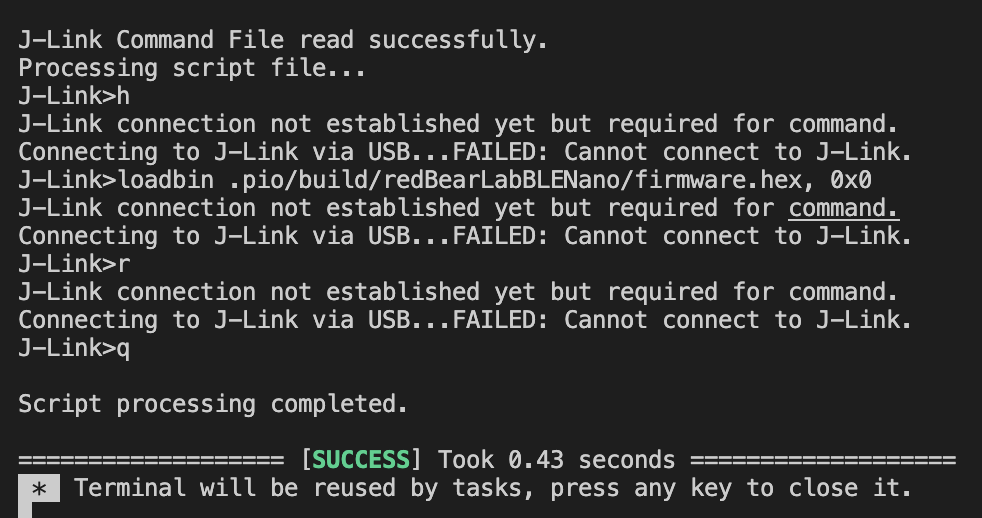
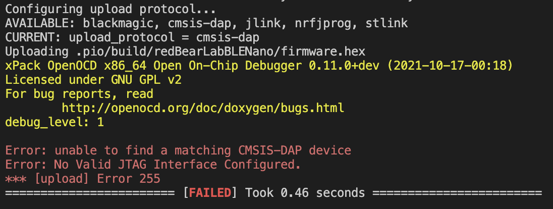
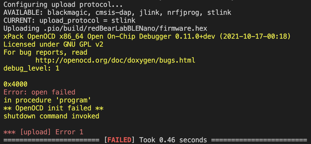
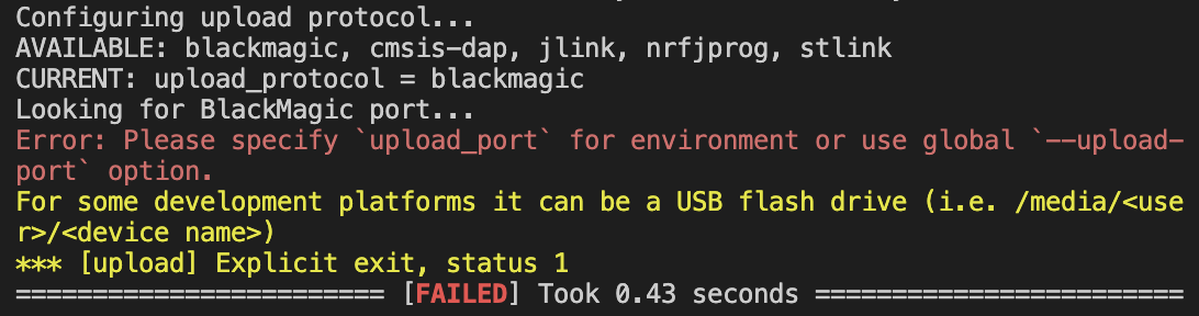
Here are the errors I got using different upload protocols:
Also, when I check my device manager, it only displays the board device in the “Port” but not in the USB section. I think the error might be caused by some bad connection. Any help is appreciated! Thanks in advance!