I got this new Uno board from WeMos with the ESP-32 chip.

I can’t find anything online. Can PIO add it to the boards?
I got this new Uno board from WeMos with the ESP-32 chip.
I can’t find anything online. Can PIO add it to the boards?
Arduino apparently gets it in under ‘ESP 32 Dev Module’.
The board is not explicitly supported. But as you have already figured out, using ESP 32 Dev Module will work fine.
The constant LED_BUILTIN might not be defined though. If I’m not mistaken, the LED pin 2. So:
static const uint8_t LED_BUILTIN = 2;
#define BUILTIN_LED  LED_BUILTIN // backward compatibility
Thank you. Reply must be at least twenty characters.
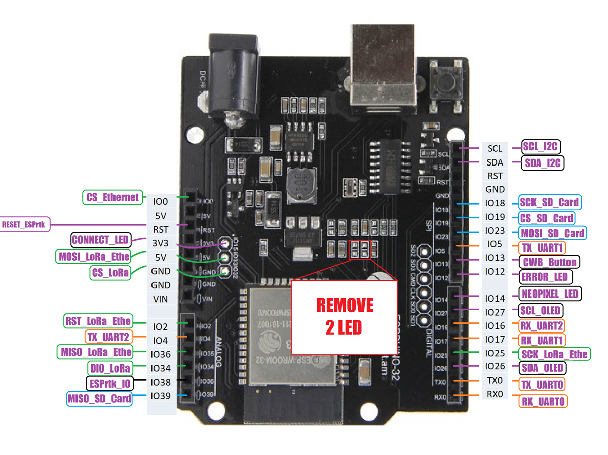
I found a pinout with several pins labeled ‘LoRa’.
There’s a CS, RST_LoRa_Ethernet, MISO_LORA_ETHER.
That pinout has nothing to do with the ESPDUINO-32 / Wemos “TTGo” D1 R32 - but some custom GPS-based high precision positioning system - where they describe how to connect their board to the ESPDUIONO (about half-way down the page). Ok, maybe that is a bit… sharp. The notation in the grey box IS related - but none of the LORA, UART, SPI, NEOPIXEL, Button, etc stuff.
btw, for what it’s worth, it looks like the Wemos D1 R32 isn’t an official product - according to cnxsoft.
It’s unfortunate it doesn’t seem to have been popular enough for someone to have done a pinout diagram for it, as it looks like a handy board to have in a drawer ![]()
So this has been around for a while?
And it was a flop?
I think it will become my Uno when I learn to use the ESP32.
Seems that way… came out in late 2017. Dunno why it didn’t really take off as it certainly has it’s use as a ESP32 uno 
Something to watch out for with these boards. I purchased a couple on Amazon (03/2021) and found that the power supply circuit attached to the barrel connector does not to appear to supply good power. Basically the ESP32 will not start a previously uploaded program is you just power the unit with a power brick attached to the barrel connector. I tried multiple different power bricks of different voltage between 9 and 12 volts, different current ratings and nothing works until it appears you add power from micro usb connector. I can power the board via the 5 volt broken out pin using an external power supply that is powered from the same wall warts and that work fine. But no go via the barrel connector unless you kick it via the USB, you can remove the USB after that. I don’t believe it is a communication thing required via the USB, rather a power problem, I can get the program to start if I power from barrel connector and just plug in a micro USB wall wart into the micro USB port for a second or two.
I was looking for a ESP32 form factor that I could use in some of my old Arduino test rigs.
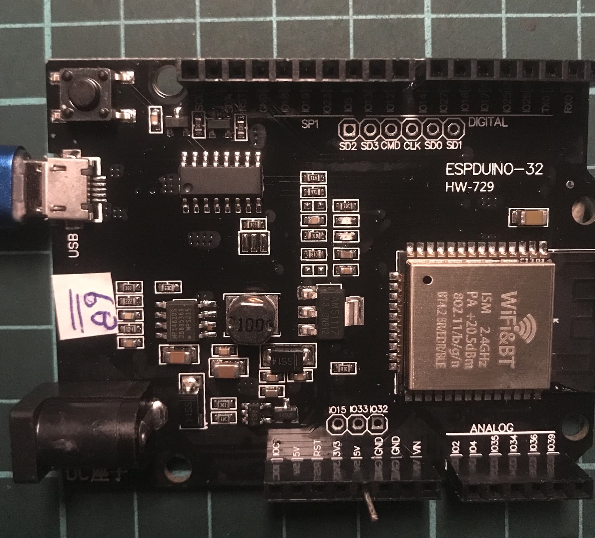
I bought 4 boards of ESP32 D1 R32 from different suppliers to test. All have different print label so I assume they probably are made from different factories.
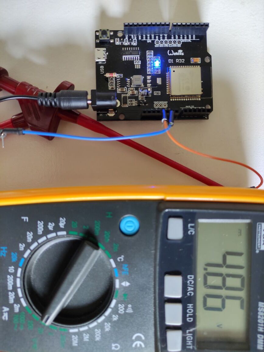
Output voltage of 4.3-4.6 volt at 5 Volt pin is somehow intentional by design. I found that the 5V pin on the board has to be left alone and the board will work fine. If you feed 5V supply voltage to 5V pin, the board will not work and WiFi will be unpredictable and serial port will have problem. If you draw current from 5V pin to drive load such as LED or buzzer, the board will be unpredictable too. The board is often freezed if I mess around with this 5V pin. At first I thought the board is malfunction but it cannot be the same for all.
If you leave this 5V pin untouched, the board will work well as charm. Do not worry about 4.3-4.6 volt that you can measure from this 5V pin. Leave it alone and it will work very well. It took me a while to find out this.
If I need 5V to feed my load, I add a separate cheap LM7805 to give my 5V load and sensor.
Power 9-12 Volt adapter to the board 2 ways either via the 2.5 mm Jack or Vin PIN.
I love this form factor as it is complete in itself. I do not have to buy the base. Just mount besides breadboard. I can even use simple wire I cut myself at any length without using Dupont pair wire because the board connectors are all female type. Lastly, it is cheaper than other form factors on AliExpress.
Only do you have to know the trick of 5V pin. I think they should remove this pin so it do not confuse people. I cannot explain the reason for this finding because I do not have schematic of this board. I guess it may have to do with RS232 chip but I do know for sure. If anyone know the answer why, please share with all of us.
Hi , I have also ordered 3 ESP32 Wemos D1 R32 , what i got was kinda the same but different labels.
I have tested one and it worked same as other esp32 boards i tested before . I have tested to power the board from usb and 12V and it was correctly functioning in both cases . I have also attached ws2812b leds to the board ( leds are powered from the board 5v pin ) and i haven’t faced any issue .
Could it be that you guys have got some bad boards somehow ? i still haven’t tested the other 2 boards as i thought i will keep them in the packing in case there is actually a hw issue and in that case i would return them . It is still the case that having the 12V input in the board is good option in some projects but i just realized that the board size is actually too big for my projects and enclosures and hence i personally think that it may not be really a useful option ( even though it is really very cheap ) . Cheers
I just wanted to thank you for this explanation about the barrel connector problem that you experienced. I have experienced exactly the same problem and was hoping somone would be able to verify the problem.
Hi,
I had the same issue with some of my boards: 5V is more like 3.8V and the 3.3V is more like 2.8V. These are cheap boards I bought on ebay, the boards themselves work fine if powered from the 12V barrel. Peripheral devices however are more critical, however most of them work. I like these boards, since I can use 12V for external devices and don’t need an extra voltage regulator.
During the weekend I did some measurements and found out the following:
Although I did not try yet, I see two solution:
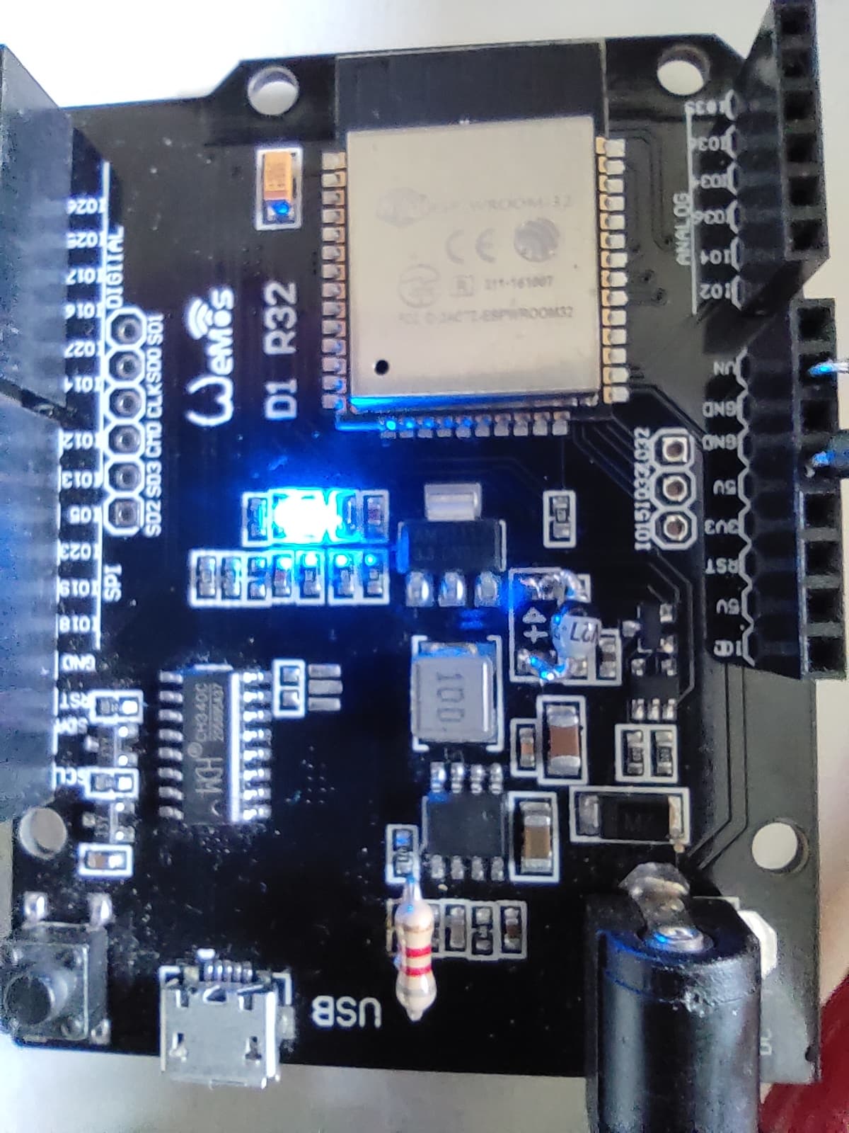
Hi, I adapted my boards by taking off the normal diode and replace it with a shottky type. Furthermore I adapted the voltage divider resistor (on board is a 10k resistor, I replaced it with a 8K resistor.
The output is now a nice 4.9V. The 3.3V output reads 3.33V.
So that seems to be fixed although soldering such small components is a real challenge!
So if you really want, you can make these boards work like it should ![]() Hope this might help.
Hope this might help.
Hi jwtielen… thanks for your pics, which Shottky diode did you use?