Hi PlatformIO
I am trying to program a ESP32-WROOM-32E module. Previously I was programming using an ESP32_DEVKITC-32D development kit with an USB port. Now I am programming directly thru the JTAG pins.
To connect, I am using a device called the TinyFPGA programmer. At the website
It is described as instead of using the “FTDI2232 USB interface chip it uses a PIC16F1455 USB microcontroller.”
Using platformio device list I get:
/dev/ttyACM0
Hardware ID: USB VID:PID=1209:2101 LOCATION=1-13:1.0
Description: Programmer
I do not see this listed in the PlatformIO at
https://raw.githubusercontent.com/platformio/platformio-core/master/scripts/99-platformio-udev.rules
And, when I try to upload I get the error message:
Warning! Unknown upload protocol ftdi
Can you add this device to your rules, and if not, can you recommend a programmer I can buy which is more universal and compatible?
Thanks for you help
With what openocd commands or tools are you programming the ESP32 through this chip? I don’t see it being supported by openocd, at least the version the ESP32 platform uses.
To me it seems like someone hacked together an FPGA specific (TinyFPGA A-Series) JTAG programmer as a microcontroller project.
If you are looking for an inexpensive JTAG programmer supported by OpenOCD and PlatformIO, your options are:
Also see:
https://medium.com/@manuel.bl/low-cost-esp32-in-circuit-debugging-dbbee39e508b
Thanks for you comments. Max, I think you are right, the TinyFPGA is specific to the TinyFPGA chips. I have purchased an ESP-PROG board and will use that.
Another confusion is that I thought firmware upload is thru the JTAG port. However, the ESP-PROG board uses UART for upload and the JTAG for debugging on two different connectors. I don’t even know if it is possible to upload thru the JTAG.
Thanks again
If your JTAG port is connected to your ESP32 module, you can upload firmware via JTAG. Just specify (in platformio.ini):
upload_protocol = esp-prog
If you have an ESP32 module (and not a development board), you can connect the ESP-Prog’s UART port to the ESP32’s UART0 pins (GPIO1 and GPIO3) and upload firmware via the serial port that appears when you connect the ESP-Prog.
If you have a development board, this is not possible as GPIO1 and GPIO3 are already connected to the USB-to-UART chip. Instead, you can upload firmware using the serial port that appears when you connect the development board.
Thanks for your help. I intend to try the JTAG method of uploading firmware soon, but I have been trying to upload over UART (using the programming port on ESP_PROG.) Unfortunately, I must activate EN manually, so I have found I must
- Ground GPIO0
- Momentarily ground EN
- proceed with upload
This does seem to communicate, as can be seen in the following snippet. However, the firmware upload does not proceed. This is using the PlatformIO for the upload.
Do you have ideas on what might be going wrong?
Thanks much, Kevin
Uploading .pio/build/esp32dev/firmware.bin
esptool.py v2.6
Serial port /dev/ttyUSB1
Connecting…
Chip is ESP32D0WDQ5 (revision 1)
Features: WiFi, BT, Dual Core, 240MHz, VRef calibration in efuse, Coding Scheme None
MAC: 10:52:1c:88:52:40
Uploading stub…
Running stub…
Stub running…
Configuring flash size…
Warning: Could not auto-detect Flash size (FlashID=0xffffff, SizeID=0xff), defaulting to 4MB
Compressed 15872 bytes to 10319…
A fatal error occurred: Timed out waiting for packet content
*** [upload] Error 2
Indeed, you need to take care of GPIO0 and EN. I’m not familiar with the exact procedure but I know that all the ESP32 developer boards have a reset circuit like this one:
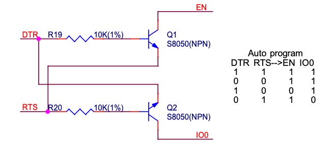
As you can see, GPIO0 and EN are controlled from the DTR and RTS signals. And the upload tool esptool.py indeed controls these lines to reset the CPU and put it in upload mode.
The reset circuit is mainly needed to ensure the CPU is not reset if the serial connection is disconnected (DTR and RTS are high by default is the serial connection is active, and low when it’s inactive).
Try to connect EN to RTS and GPIO0 to DTR. Make sure GPIO2 is floating or pulled low.
For more details, also see:
Thanks for the response. Thru a miracle of patience, I did manage to connect EN to my ESP32-WROOM-32E module. So now both EN and GPIO0 are connected to the ESP-PROG board, but the firmware upload always fails at the same place. I’m stuck, so now I will try the JTAG upload, although I do not see why it would make a difference.
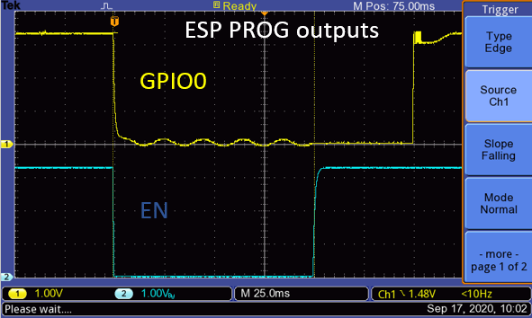
I attach an oscilloscope trace of what ESP-PROG does with the EN and GPIO0 pins for your amusement.
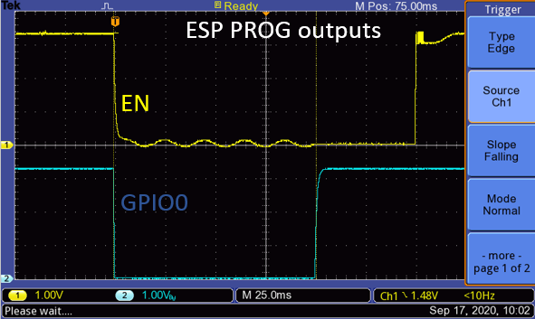
Ooops, sorry I mislabeled those. Exactly opposite; here are the correct labels
To finish this topic, I was able to solve the problem. To summarize the problem, I was programming my EP32-WROOM-32E module using only the program port (UART) of my ESP-PROG board. Since the module is already installed on a circuit board, I had difficulty connecting the EN pin (which is part of the ESP-Prog connector), but eventually got it. However, the firmware upload would fail and afterwards the message
rst:0x10 (RTCWDT_RTC_RESET),boot:0x33 (SPI_FAST_FLASH_BOOT)
invalid header: 0xffffffff
would continuously come from the ESP32. I eventually found that GPIO12 was high, which means that the chip was in 1.8 V mode instead of the desired 3.3 V:

I am not sure why, since GPIO12 should be pulled low by default and my circuit has it unconnected. Nevertheless, I pulled it to ground (thru a 100 Ohm resistor) and now the circuit boots normally. Now on to the next problem!
1 Like