I am trying to understand the STC15W408AS mcu, but I need help, can anybody give me an idea of what hardware I need to connect from my pc (Windows 10) to the mcu to download a program. I have always used an Arduino UNO or nano which has a USB connection.
many thanks
When using board = STC15W408AS, it uses the upload protocol stcgal. Per project description at
this program can communicate with a bootloader that’s burned into the STC chips over UART and USB.
Looking at a board like https://aliexpress.com/item/1005001689967942.html
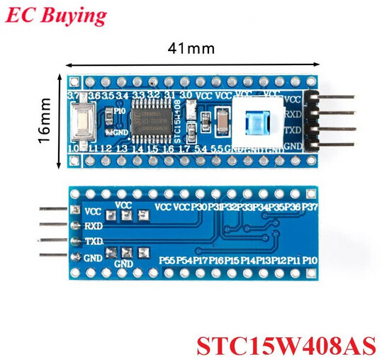
it is very clear that they want you to connect a USB-to-UART adapter to the VCC, RXD, TXD, GND pin, for Power + UART connection. You should have a USB-to-UART for that, such as an FTDI FT232R (Amazon), CP2102, CH340, etc.
If you don’t have such an adapter (which is in any case highly recommendable), you can also reuse the USB-serial adapter as found on the Arduino Uno, Nano etc. All you have to do is connect the RESET pin to GND (so that the ATMega328p chip doesn’t do anything but only the usb-to-uart chip does) and then use RX->RXD, TX->TXD. See here. You can also supply the target board with GND and 5V that way.
Yes I have a FTDI, but what I need is to program a 28 DIP

stc15w408as, so not sure that using the unit from Ali-express will work.
The schematics of the board are trivial.

If you have just the chip in its DIP package, just find the VCC, GND, RXD (P3.0), TXD (P3.1) on the chip and connect up your USBt-to-UART adapter there. See e.g. here.
Just to make things clearer maybe:
If you have an FTDI: Great. Note that the wiring should be between FTDI ↔ STC
- 5V ↔ VCC
- GND ↔ GND
- RX ↔ TXD
- TX ↔ RXD
The RX->RX was only a special case if you were to reuse an Arduino Nano/Uno.
Also note that per series datasheet, page 12, it seems that the chip is only briefly in bootloader mode after powerup. So before triggering an upload, the target chip should be powered off (e.g. 5V not actually connected), then as it’s uploading you need to give it power. Hence why the dev board schematics above has a latching switch (SW) that connects or disconnected the “VCC” pin to the “MVCC” (microcontroller VCC), exactly for that.
Exact data sheet here also shows DIP28 pinout. (STC12W408AS shows up in the “STC12W401AS series” table)

Thank you very much for the extra info, will look into it. Will I still have to use the stcgal, not sure I understand this bit, is it something that goes in the platformio.ini file. sorry
STCGAL is already the default upload protocol in the board definition. So really all you need to do is create a normal project for the “Generic STC15W408AS” board and it should give you a standard
[env:STC15W408AS]
platform = intel_mcs51
board = STC15W408AS
You should totally try and upload an empty program first to see if you can upload at all.
int main()
{
  while(1) {}
  return 0;
}
Then you can look into including the right header for the STC12W408AS and accessin its special function registers to facilitate a GPIO blinky etc, such as used in the anymcu-blink project.
Thank you so much for the information.
Will try over the Christmas period.
Decided to try the empty program just connecting the FTDI board (waiting for the STC chips to arrive) So:
When I start Platformio I always get this message:
[12/11/2023, 2:52:00 PM] Unable to resolve configuration with compilerPath "C:/Users/Richard/.platformio/packages/toolchain-sdcc/bin/sdcc.exe". Using "C:/Users/Richard/.platformio/packages/toolchain-xtensa-esp32s3/bin/xtensa-esp32s3-elf-gcc.exe" instead.
Can’t seem to get rid of this!
Then when I try to run something I get this Output EVERY time:
Error: The PlatformIO task detection didn’t contribute a task for the following configuration:
{
    "type": "PlatformIO",
    "task": "Pre-Debug (arduino_nano_esp32)",
    "problemMatcher": [
        "$platformio"
    ],
    "label": "PlatformIO: Pre-Debug (arduino_nano_esp32)"
}
The task will be ignored.
Again can’t seem to resolve this!
Good news if think is:
running the Empty program just to the FTDI…
 *  Executing task in folder 231210-105700-stc-test: C:\Users\Richard\.platformio\penv\Scripts\platformio.exe run --target upload

Processing STC15W408AS (platform: intel_mcs51; board: STC15W408AS)
-------------------------------------------------------------------------------------------------------------------Verbose mode can be enabled via `-v, --verbose` option
CONFIGURATION: https://docs.platformio.org/page/boards/intel_mcs51/STC15W408AS.html
PLATFORM: Intel MCS-51 (8051) (2.1.0) > Generic STC15W408AS
HARDWARE: STC15W408AS 11MHz, 512B RAM, 8KB Flash
PACKAGES:
 - tool-stcgal @ 1.106.0 (1.6)
 - tool-vnproch55x @ 1.0.220407
 - toolchain-sdcc @ 1.40200.0 (4.2.0)
LDF: Library Dependency Finder -> https://bit.ly/configure-pio-ldf
LDF Modes: Finder ~ chain, Compatibility ~ soft
Found 0 compatible libraries
Scanning dependencies...
No dependencies
Building in release mode
Checking size .pio\build\STC15W408AS\firmware.hex
Advanced Memory Usage is available via "PlatformIO Home > Project Inspect"
Flash: [          ]   1.3% (used 104 bytes from 8192 bytes)
Configuring upload protocol...
AVAILABLE: stcgal
CURRENT: upload_protocol = stcgal
Looking for upload port...
Auto-detected: COM8
Uploading .pio\build\STC15W408AS\firmware.hex
Cycling power: done
Just waiting for the boards now.
This is because inherently, VSCode does not officially recognize SDCC as a compiler (that’s the one being used for all Intel-8051 core stuff). That has also not changed in the 2 years since I requested it.
As a result, Intellisense does not fully work in VSCode for Intel-8051 and SDCC specific things like “special function register” declarations. However, it should still well enough for basic intellisense and editing code. There are some workarounds for that in e.g. https://github.com/platformio/platform-intel_mcs51/issues/45 and https://github.com/microsoft/vscode-cpptools/issues/2499. For now, you shouldn’t worry about them too much. If VSCode shows red squiggles but PlatformIO compiles the program with SDCC just fine, the program is valid.
This seems to be coming from another project (arduino_nano_esp32)? You may need to remove that project from the VSCode workspace (rightclick on folder). In any case, these old Intel 8051 cores do not really support live-debugging the chip (without hacks), but uploading should work just fine.
Ok great I will live with the first one…
The second one I found a task.json file in C:…projects\test_nano_esp32.vscode and deleted it. Now the it doesn’t run that task, so I’m good.
Now I will wait for the STC15W408AS chips to arrive. Thanks you so much for your help.
Hi, Just an update…
Received stc15w408as chips, Set up with FTDI , put led on P1.0 switched on, chip already programmed with flashing led. Used the anymcu-blink program and adjusted delay (just to check) and up loaded, powering the chip when the uploading was ready, yes everything went well. According to the data sheet, the outputs are High when starting but I can’t find how to change this so outputs are Low when powering up. I know that the outputs are “quasi_bidirectional/weak pull-up (traditional 8051 I/O ports mode) after reset, and can be set to four modes: quasi_bidirectional /weak pull-up, strong pushpull/ strong pull-up, input-only/high-impedance and open drain” (copied) don’t know if you could help, Regards Richard
Sounds great!!
This seems weird. On powerup / power on reset, all GPIO pins should be INPUT and not OUTPUT, as to not drive something that should not be driven. If the GPIO is in input before mode before you change it, you should first change the GPIO data register to have a 0-bit for the GPIO pin position and THEN change the GPIO mode register to change it from input to output. It should output LOW without outputting HIGH first.
Understand what you are saying, but just can’t figure out how…
26/18/14 common I/O ports are available, their mode is quasi_bidirectional/weak pull-up (traditional 8051
I/O ports mode) after reset, and can be set to four modes quasi_bidirectional/weak pull-up, strong push-pull/
strong pull-up, input-only/high-impedance and open drain.
:
Got this from : General Overview of STC15W401AS series MCU
Hi, I have just found this info about setting the Port (bit) on the STC15w*** mcu and I understand what it is doing, setting P1.(0-7) bit using P1M1 and P1M0 but what I can’t see where or how to program it in PlatformIO What I need to do is set P1.7 and P1.6 as input only (P1M1 =1 P1M0 =0) and P1.0 and P1.1 as Push/Pull (P1M1 =0 P1M0 =1). The code I think is MOV P1M1 = #11000000B MOV = #00000011B Can anyone help as to where or how I should put code. Many thanks

The MOV is assembly code, in C code it would just be an assignment as something like
P1M1 = 0xA0; // 10100000
P1M0 = 0xC0; // 11000000
Assuming P1M1, P1M0 have been declared as a special function register somewhere.
#define _P1 0x90
SFR(P1, 0x90);          //1111,1111  port 1

SBIT(P10, _P1, 0);
SBIT(P11, _P1, 1);
SBIT(P12, _P1, 2);
SBIT(P13, _P1, 3);
SBIT(P14, _P1, 4);
SBIT(P15, _P1, 5);
SBIT(P16, _P1, 6);
SBIT(P17, _P1, 7);
#define _P1M0 0x92
SFR(P1M0, 0x92);        //0000,0000  Port 1 Mode Register 0
#define _P1M1 0x91
SFR(P1M1, 0x91);        //0000,0000  Port 1 Mode Register 1
Found this in STC15Fxx.h file in the project, don’t if this defines it.