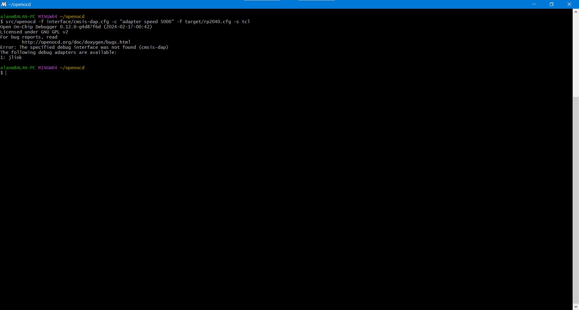
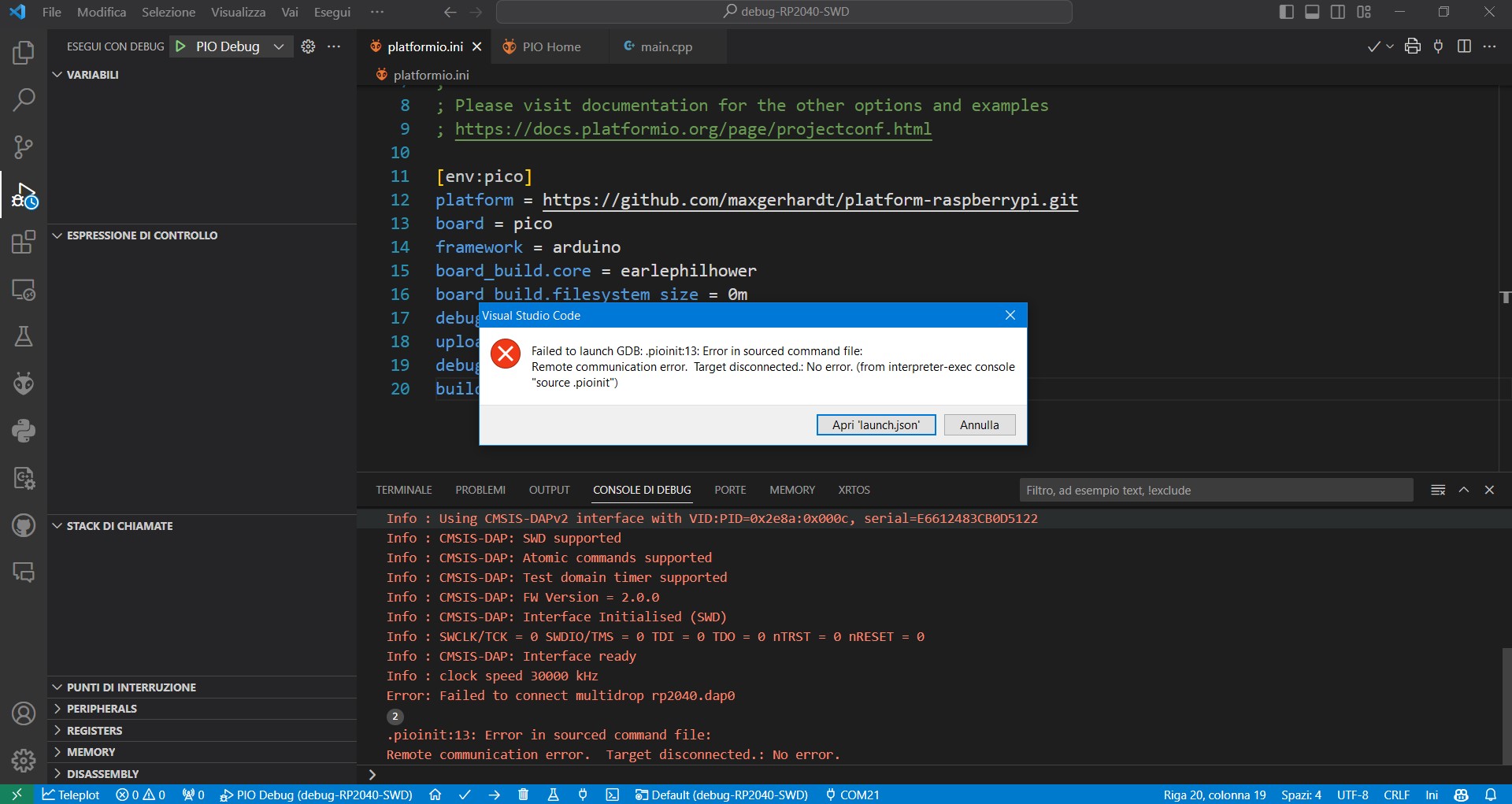
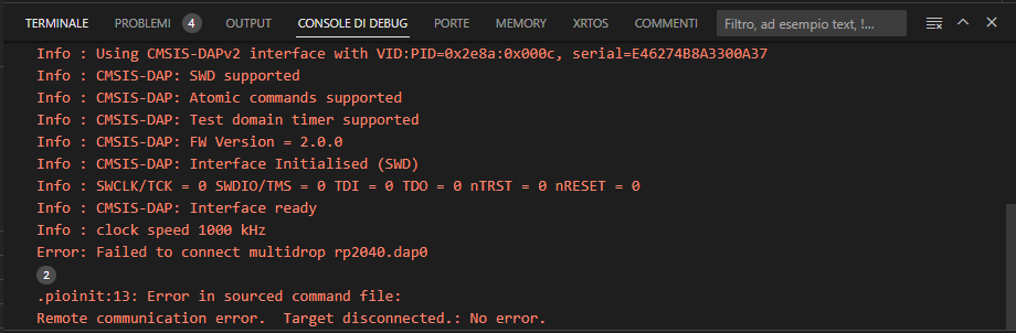
The last screenshot looks kind of good, it at least finds the debug adapter, but it was unable to connect to the target RP2040 chip. This is likely because
you did this this step wrong, the debugprobe.uf2 is for the “Debug Probe” hardware and changes the SWDIO/SWCLK pinout. (GP2/3 for SWCLK/SWDIO in picoprobe.uf2, GP12/14 for debugprobe.uf2)
You need to flash the picoprobe.uf2 on your regular Pi Pico.
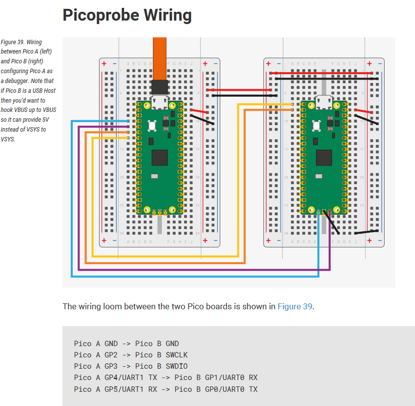
Make sure to follow the right pinout then as documented, if not already the case.
So now I check another time the wiring and I made another test, so I uploaded a blink program on the DUT whit classical method, then I connected it to the debugger and noting seems working, so I measure Vin voltage and the surprise: my second board is not the official one and VSYS pin has not the VSYS volt because is called Vin (later I’ll check what is exactly) so it didn’t power on the target RP2040!!
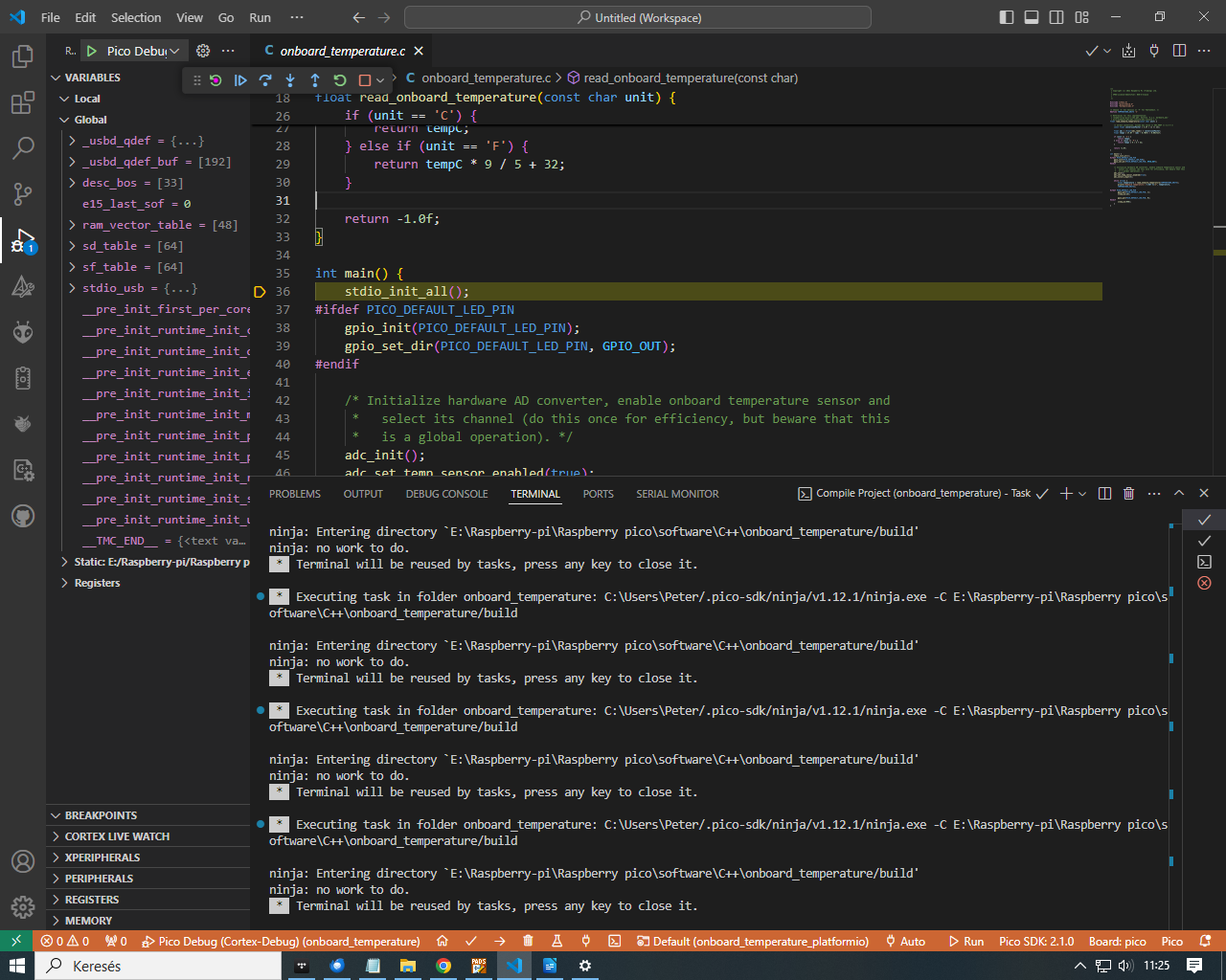
Would you please send me the exact circumstances how it works. I have a same hardware 2 rp2040 that works under VScode Using an Raspberry Pico as picoprobe debugger for another RP2040. Same hrdware as in the picture
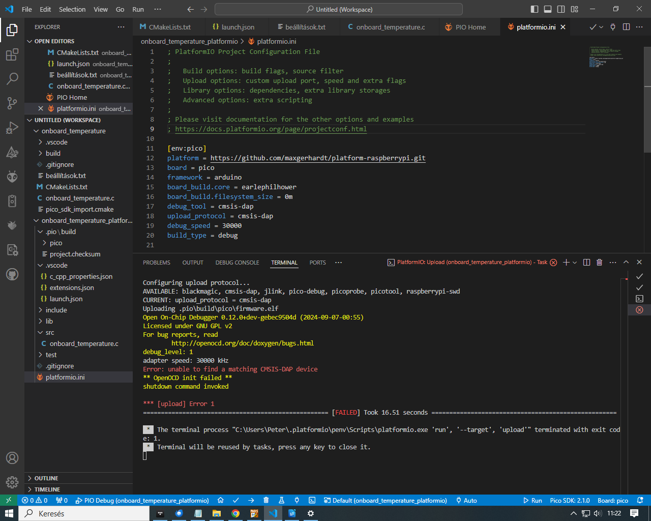
I Works fine under SDK ver 2.0.0 with Pico Debug(Cortex debug), but not under platformio PIO debug
undefinedC:\Users\Peter.platformio\packages\toolchain-gccarmnoneeabi\bin\arm-none-eabi-gdb.exe: warning: Couldn’t determine a path for the index cache directory.
Reading symbols from e:\Raspberry-pi\Raspberry pico\software\C++\temperature\onboard_temperature\onboard_temperature_platformio.pio\build\pico\firmware.elf…
This should already work with the wiring provided above plus the latest firmware from https://github.com/raspberrypi/debugprobe/releases, e.g., debugprobe_on_pico.uf2. If you have problems, post your platformio.ini, wireup, and output of pio debug --interface=gdb -- -x .pioinit from the CLI.
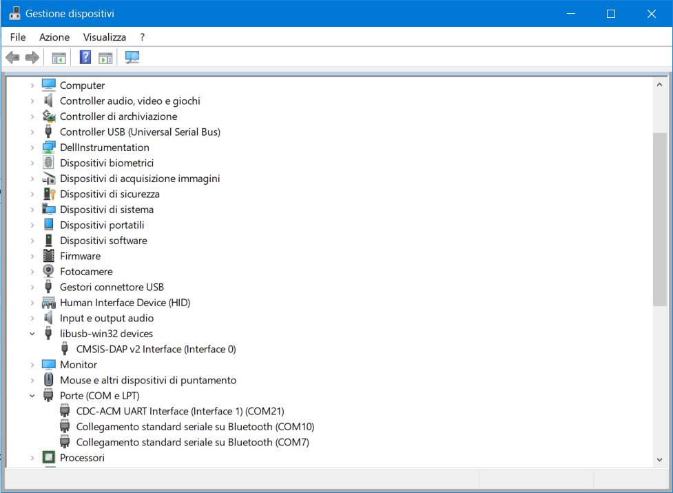
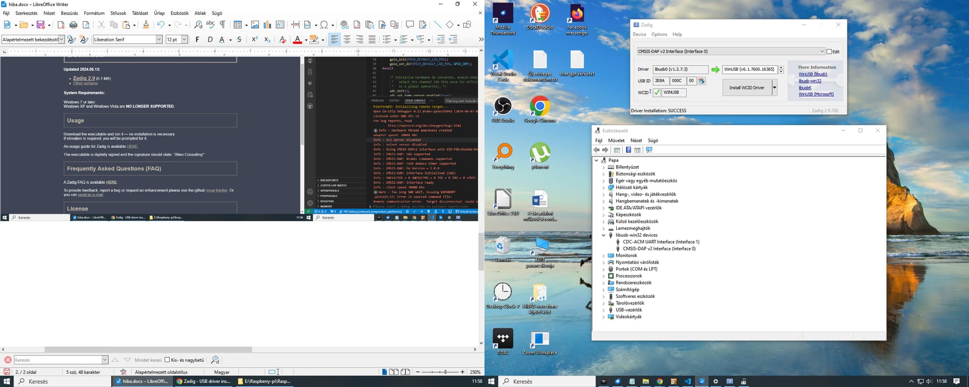
Screenshot of https://zadig.akeo.ie/ with the CMSIS-DAP device selected shows what? (The interface which should have WinUSB or libusb drivers loaded, not the serial port interface)