Hi! I’m not entirely sure what will be helpful information for this issue. I’m hoping someone can help me.
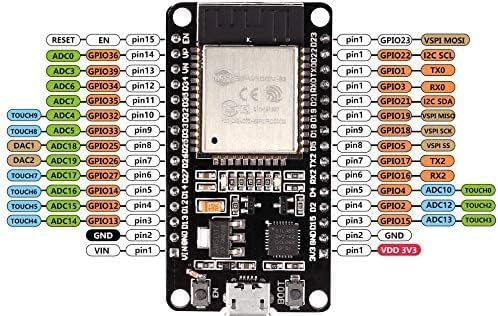
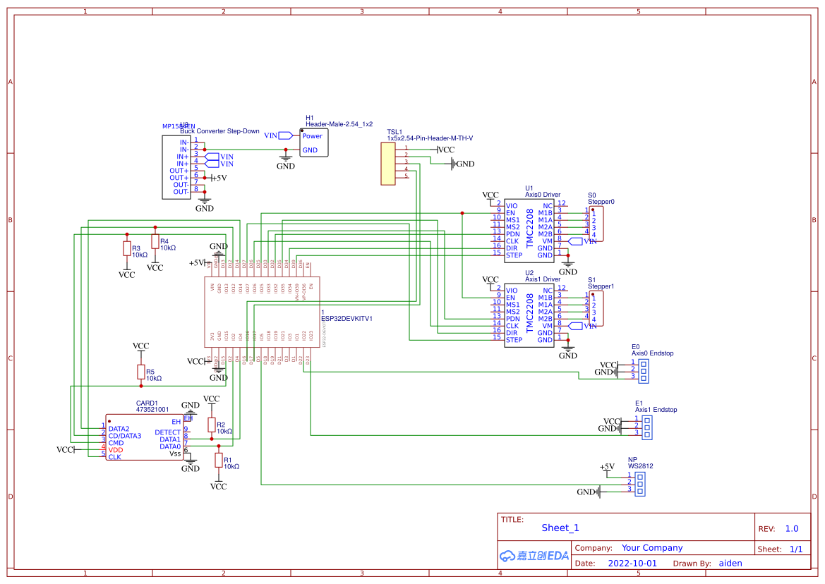
I am working on building a kinetic sand table. It’s a project I’m doing for school and I’m stuck. I’m trying to flash this PlatformIO firmware on an ESP32-WROOM-32 (ESP32-DEVKIT-V1). It will run on this custom PCB that goes along with the firmware. There is also a separate web interface that gets uploaded as a file system after being built using yarn.
The ESP32 firmware flashes fine when it is by itself and connected to my Mac via USB. But, when I have it plugged in to the PCB, I cannot flash the ESP32. Likewise, if I flash the ESP32 (including the file system) separately and then plug it in to the PCB, the board doesn’t run. Same goes with the file system: I can’t upload the file system when the ESP32 is installed on the PCB, but the file system upload works when the ESP32 isn’t installed.
Although there will be other components connected to the PCB, I have tried it only with the ESP32 and microSD card present. I have also tried it with the buck converter added and a 24V/6A power supply.
When I try to flash the board, here is the output:
Processing dev (platform: espressif32; board: esp32dev; framework: arduino)
-------------------------------------------------------------------------------------------------------------------------------------
Verbose mode can be enabled via `-v, --verbose` option
CONFIGURATION: https://docs.platformio.org/page/boards/espressif32/esp32dev.html
PLATFORM: Espressif 32 (6.6.0) > Espressif ESP32 Dev Module
HARDWARE: ESP32 240MHz, 320KB RAM, 4MB Flash
DEBUG: Current (cmsis-dap) External (cmsis-dap, esp-bridge, esp-prog, iot-bus-jtag, jlink, minimodule, olimex-arm-usb-ocd, olimex-arm-usb-ocd-h, olimex-arm-usb-tiny-h, olimex-jtag-tiny, tumpa)
PACKAGES:
- framework-arduinoespressif32 @ 3.20014.231204 (2.0.14)
- tool-esptoolpy @ 1.40501.0 (4.5.1)
- tool-mkfatfs @ 2.0.1
- tool-mklittlefs @ 1.203.210628 (2.3)
- tool-mkspiffs @ 2.230.0 (2.30)
- toolchain-xtensa-esp32 @ 8.4.0+2021r2-patch5
LDF: Library Dependency Finder -> https://bit.ly/configure-pio-ldf
LDF Modes: Finder ~ chain, Compatibility ~ soft
Found 65 compatible libraries
Scanning dependencies...
Dependency Graph
|-- ESP Async WebServer @ 1.2.3+sha.f71e3d4
|-- ArduinoLog @ 1.1.1
|-- TMCStepper @ 0.7.3
|-- FastLED @ 3.6.0
|-- SparkFun TSL2561 @ 1.1.0
|-- esp32FOTA @ 0.2.7
|-- WireGuard-ESP32 @ 0.1.5+sha.50e2bfd
|-- RdUtils
|-- RdConfigPinMap
|-- RdJson
|-- RdConfig
|-- RdRestAPISystem
|-- CommandScheduler
|-- RdFileManager
|-- RdLedStrip
|-- RdNTPClient
|-- RdRestAPIEndpoints
|-- RdWebServer
|-- RdWiFiManager
|-- WireGuardManager
|-- RdOTAUpdate
|-- WiFi @ 2.0.0
|-- SPI @ 2.0.0
Building in release mode
Retrieving maximum program size .pio/build/dev/firmware.elf
Checking size .pio/build/dev/firmware.elf
Advanced Memory Usage is available via "PlatformIO Home > Project Inspect"
RAM:   [==        ]  18.2% (used 59764 bytes from 327680 bytes)
Flash: [========= ]  91.0% (used 1371413 bytes from 1507328 bytes)
Configuring upload protocol...
AVAILABLE: cmsis-dap, esp-bridge, esp-prog, espota, esptool, iot-bus-jtag, jlink, minimodule, olimex-arm-usb-ocd, olimex-arm-usb-ocd-h, olimex-arm-usb-tiny-h, olimex-jtag-tiny, tumpa
CURRENT: upload_protocol = esptool
Looking for upload port...
Using manually specified: /dev/cu.usbserial-0001
Uploading .pio/build/dev/firmware.bin
esptool.py v4.5.1
Serial port /dev/cu.usbserial-0001
Connecting..........
Chip is ESP32-D0WD-V3 (revision v3.1)
Features: WiFi, BT, Dual Core, 240MHz, VRef calibration in efuse, Coding Scheme None
Crystal is 40MHz
MAC: 30:c9:22:32:e4:a8
Uploading stub...
Running stub...
Stub running...
Changing baud rate to 921600
Changed.
WARNING: Failed to communicate with the flash chip, read/write operations will fail. Try checking the chip connections or removing any other hardware connected to IOs.
Configuring flash size...
Flash will be erased from 0x00001000 to 0x00005fff...
Flash will be erased from 0x00008000 to 0x00008fff...
Flash will be erased from 0x0000e000 to 0x0000ffff...
Flash will be erased from 0x00010000 to 0x00160fff...
Compressed 17536 bytes to 12202...

A fatal error occurred: Packet content transfer stopped (received 8 bytes)
*** [upload] Error 2
==================================================== [FAILED] Took 13.67 seconds ====================================================

*  The terminal process "platformio 'run', '--target', 'upload', '--environment', 'dev'" terminated with exit code: 1.
*  Terminal will be reused by tasks, press any key to close it.
When I open Monitor, this output loops repeatedly:
rst:0x10 (RTCWDT_RTC_RESET),boot:0x37 (SPI_FAST_FLASH_BOOT)
invalid header: 0xffffffff
invalid header: 0xffffffff
invalid header: 0xffffffff
invalid header: 0xffffffff
invalid header: 0xffffffff
invalid header: 0xffffffff
invalid header: 0xffffffff
ets Jul 29 2019 12:21:46
I have looked so many places and haven’t been able to find the answer. If anyone can help, I would greatly appreciate it!