Hi,
I’d like to turn on an RGB led using stm32 F767ZI but it’s not working.
I’m programming the baord using PlatformIO with Arduino framework.
The led has 4 pins (GND and three other pins for RGB), I also used three resistors of 220kΩ.
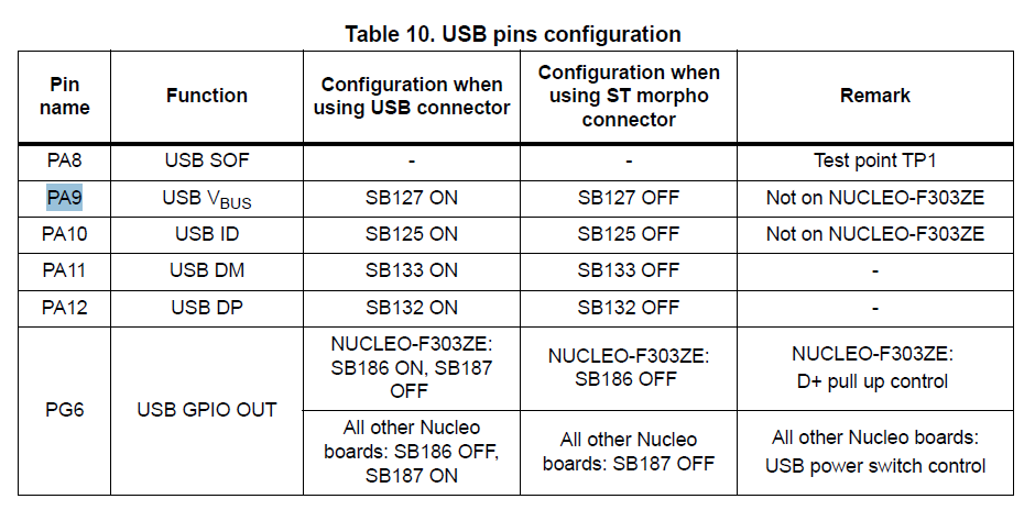
On the board I’m using pin PA10 which works (meaning the pin when activated turn the led on (red)) but all the other pins don’t (I tried PA8, PA9, PE11, PE14, PB4,PB5).
I know that they are all pwm pins but I don’t have enough analog pins to control the led so I’m using pwm pins.
My .ini file
[env:nucleo_f767zi]
platform = ststm32
board = nucleo_f767zi
framework = arduino
upload_protocol = stlink
debug_tool = stlink
build_type = debug
monitor_speed = 115200
build_flags =
	-D USE_FULL_ASSERT
	-D DEBUG
	-D SERIAL_DEBUG
monitor_port = /dev/cu.usbmodem1103
lib_deps =
	z3t0/IRremote@^4.4.1
	adafruit/Adafruit NeoPixel@^1.12.5
#include<Arduino.h>
constexpr int BLU = PA9;
constexpr int GREEN = PA8;
constexpr int RED = PA10;

void setup() {
  Serial.begin(115200);
    pinMode(BLU, OUTPUT);
    pinMode(RED, OUTPUT);
    pinMode(GREEN, OUTPUT);
}

void loop() {
digitalWrite(BLU, HIGH);
digitalWrite(RED, LOW);
digitalWrite(GREEN, LOW);
}
Only PA10 behaves as expected, the others keep the led off.
What am I doing wrong? Is there something additional to know about stm board functioning?
Using Arduino framework I would expect that timers, etc are handled internally by the lib.
Thank you.
