TTGO T3 GPIO13 looks insensitive to grounding push button

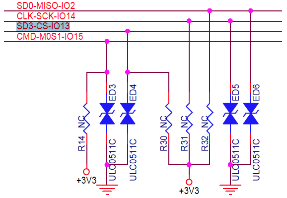
I guess this is kind of an off topic discussion in this forum, but maybe someone has already faced similar issue. I’m using a LilyGo TTGO T3_V1.6.1 (ESP32-Pico-D4) embedded in a custom PCB with a push button connected to GPIO 13 (µP pin 20).

GPIO 13 is supposed to be hardware pulled up by R30 in TTGO board:
image

I’m trying to configure GPIO 13 as a digital input and read its logical state. The pin can be grounded by pressing the push button. It might sound ridiculous, but I can’t get any reasonable answer.

Setting the pin up as INPUT, it reads always false (0).

Setting the pin up as INPUT_PULLUP, it reads always true (1), despite the push button is pressed or not.

In both cases, pin voltage readout stays around 0,2 V while push button is released.

Would there be any config register that should also be adjusted so that pinMode(...) makes effect?

Thank you.
Regards.

That resistor is labeled NC, which makes me think it’s not populated.

Is your pushbutton connecting to ground?

It’s possible. I’m gonna bring it out from the case and check the board.

Anyway, when setting pinmode( button, INPUT_PULLUP ) there should an internal resistor bringing the pin voltage high. That’s why I think there must be something missing. Maybe the TVS is faulty!

Yes, between pin and ground.

Thank you.
Regards,

Indeed the resistors aren’t there.

Nevertheless things are weird!

Even setting GPIO13 as output by pinMode( 13, INPUT) or pinMode( 13, INPUT_PULLUP, nothing changes.

I’ve compared behaviors between GPIO13 and GPIO12, serial printing digitalRead, touchRead and analogRead of both. The code doesn’t initilize GPIO12 as input or output. By default, I guess it should be input.

Side by side, they show the same behavior.

For analogRead both return reasonable values between 0 and 4095, responding to voltage, except when WiFi is active. Then they return error.

Both always returns “0” for digitalRead and some value between 30 and 80 for touchRead when their respective grounding push buttons are released.

When the push buttons are pressed, touchRead returns “0” for both.

What I cal weird is that even connected directly to 3.3V, digitalRead always returns “0”.

It looks like pinMode setup does absolutely nothing!

Regards,

As a sanity test, can you check that the pin can be used as an output and toggle it up and down? It’s possible that there’s a wiring error or somehow the pin got blown out…

Pullup/down not avail on some pins? are 'straps' permanent? - ESP32 Forum says it’s a silicon bug that is worked around in ESP-IDF… not sure if Arduino-ESP32 has the same patch.

Do you see the same behavior in the Arduino IDE and the latest 2.0.1 core?

Hello @maxgerhardt

Good idea!
in Arduino IDE 2.0.0 for Windows, these I/O pins work perfectly as INPUT_PULLUP.

Thank you.

I guess in PlatformIO I’ll have to set them up via configuration registers.
Is someone used to do it?

Regards

You can try and use core version 2.0.0 (or also 2.0.1) in PlatformIO by changing your platform = espressif32 to

platform  = https://github.com/platformio/platform-espressif32.git#feature/arduino-idf-master

and adding

platform_packages  = framework-arduinoespressif32 @ https://github.com/espressif/arduino-esp32.git#2.0.1
                     platformio/tool-esptoolpy @ https://github.com/tasmota/esptool/releases/download/v3.2/esptool-v3.2.zip

to the bottom of your platformio.ini. Does it then ‘magically’ work?

Thank you @maxgerhardt

I’m trying to follow your instructions. But I guess I’ll need further help.

Because of that issue of TTGO T3 board with WCH CH9102F USB interface, I was forced to move the code to VSCode for Windows. I’m not used to Windows anymore and I’ve been going through hard times with it.

So, after including those paths in platformio.ini, I’ve tried to build the code and then an error message came up:

Platform Manager: Installing git+https://github.com/platformio/platform-espressif32.git#feature/arduino-idf-master
Error: Please install Git client from https://git-scm.com/downloads

I’ve downloaded this application and started its installation. After some minutes, the installer has asked to choose an editor:
image

I’ve chosen Visual Code Insiders, with no specific reason. I had to chose one.

I’ve downloaded and installed this VS Code Insiders and nothing else has happened. This “Next” button kept in gray mode.

I was afraid it would go through those Windows endless installation procedures. So, I’ve clicked “Back” again and again until the beginning and started it again. This time, it has let me click “Next” and to “chose” many further options page after page.

Nevertheless, nothing changed.

Should I have really installed this application? Should I check something else?

Thank you.
Regards,
Ciro.

When I use Windows I have the feeling that things can always get even worse.

I’ve decided to do Windows magic trick of turning everything off and on again. After starting VSCode again, I’ve asked for building the code again. Then it took a while for installing esptool:

Tool Manager: Installing git+https://github.com/tasmota/esptool/
git version 2.34.1.windows.1

But at the end, there was another error:
Error: Could not find one of 'package.json' manifest files in the package

How can I go on now?

Thank you.
Regards, Ciro.

This doesn’t look good, it’s supposed to pull it from

not the raw repo.

Again, trying to find out how to configure digital inputs and output through ports registers, I’ve been trying to apply pinMode commands to three different GPIOs and check its effect over some registers. But regardless the pin mode selected, it seems I’m watching the wrong registers.

The code I’ve been using is:

uint8_t fase = 0;
  #define output          0
  #define input           1
  #define input_pulldown  2
  #define input_pullup    3

void print_reg(void)
{
  Serial.print("\nGPIO_IN_REG : 0b");       Serial.print(GPIO_IN_REG, BIN);
  Serial.print("\tGPIO_ENABLE_REG : 0b");   Serial.print(GPIO_ENABLE_REG, BIN);
  Serial.print("\tIO_MUX_GPIO25_REG : 0b"); Serial.print(IO_MUX_GPIO25_REG, BIN);
  Serial.print("\tIO_MUX_GPIO12_REG : 0b"); Serial.print(IO_MUX_GPIO12_REG, BIN);
  Serial.print("\tIO_MUX_GPIO13_REG : 0b"); Serial.print(IO_MUX_GPIO13_REG, BIN);
}

void setup (void)
{
  Serial.begin(115200);
  delay(500);
  Serial.print("Configuração inicial:");
  print_reg();
}

void loop (void)
{
  switch (fase) {
    case output:
      pinMode(25, OUTPUT);  pinMode(12, OUTPUT);  pinMode(13, OUTPUT);
      Serial.print("\nOUTPUT:");
      break;
     case input:
      pinMode(25, INPUT);   pinMode(12, INPUT);   pinMode(13, INPUT);
      Serial.print("\nINPUT:");
      break;
     case input_pulldown:
      pinMode(25, INPUT_PULLDOWN);  pinMode(12, INPUT_PULLDOWN);  pinMode(13, INPUT_PULLDOWN);
      Serial.print("\nINPUT_PULLDOWN:");
      break;
     case input_pullup:
      pinMode(25, INPUT_PULLUP);    pinMode(12, INPUT_PULLUP);    pinMode(13, INPUT_PULLUP);
      Serial.print("\nINPUT_PULLUP:");
      break;
    default: break;
  }
  
  delay(1000);

  print_reg();

  if (++fase > 3) fase = 0;
}

And the results I’ve been cyclically obtaining are:

OUTPUT:
GPIO_IN_REG : 0b111111111101000100000000111100	GPIO_ENABLE_REG : 0b111111111101000100000000100000	IO_MUX_GPIO25_REG : 0b111111111101001001000000100100	IO_MUX_GPIO12_REG : 0b111111111101001001000000110100	IO_MUX_GPIO13_REG : 0b111111111101001001000000111000
INPUT:
GPIO_IN_REG : 0b111111111101000100000000111100	GPIO_ENABLE_REG : 0b111111111101000100000000100000	IO_MUX_GPIO25_REG : 0b111111111101001001000000100100	IO_MUX_GPIO12_REG : 0b111111111101001001000000110100	IO_MUX_GPIO13_REG : 0b111111111101001001000000111000
INPUT_PULLDOWN:
GPIO_IN_REG : 0b111111111101000100000000111100	GPIO_ENABLE_REG : 0b111111111101000100000000100000	IO_MUX_GPIO25_REG : 0b111111111101001001000000100100	IO_MUX_GPIO12_REG : 0b111111111101001001000000110100	IO_MUX_GPIO13_REG : 0b111111111101001001000000111000
INPUT_PULLUP:
GPIO_IN_REG : 0b111111111101000100000000111100	GPIO_ENABLE_REG : 0b111111111101000100000000100000	IO_MUX_GPIO25_REG : 0b111111111101001001000000100100	IO_MUX_GPIO12_REG : 0b111111111101001001000000110100	IO_MUX_GPIO13_REG : 0b111111111101001001000000111000

This code was run in Arduino 2.0.0-beta.7 because, for some reason, with VSCode+PlatformIO the code seems not to be flashed.

Given these results, which might be the registers affected by “pinMode” command?

Please help.
Thank you.
Regards,
Ciro.
The matter here it that the compiler doesn’t allow the register to be read or written as a variable.

So, doing so I can get just the register’s address itself (0b111111111101000100000000111100).

As far as I can remember, in Arduino environment it is/was possible to read and write directly on the registers through their mnemonics.

Anyway, I guess I’ve got to find out another way.

I’ve been thinking of doing so via pointers. I’ve been trying, but I haven’t been able to attribute the register’s address (a constant) to the pointer . Neither can read the address the pointer points to.

  uint32_t conteudo;
  uint32_t *reg_PTN;

  reg_PTN = (uint32_t) GPIO_ENABLE_REG; //  #define GPIO_ENABLE_REG (DR_REG_GPIO_BASE + 0x0020) | #define DR_REG_GPIO_BASE 0x3ff44000
  conteudo = *reg_PTN;

  Serial.print("\nGPIO_ENABLE_REG = 0x"); Serial.print( reg_PTN, HEX);
  Serial.print("\tConteudo = 0b"); Serial.print (*reg_PTN, BIN);

The error messages are:

src\main.cpp:8:11: error: invalid conversion from 'uint32_t {aka unsigned int}' to 'uint32_t* {aka unsigned int*}' [-fpermissive]
   reg_PTN = (uint32_t) GPIO_ENABLE_REG; //  #define GPIO_ENABLE_REG (DR_REG_GPIO_BASE + 0x0020) | #define DR_REG_GPIO_BASE 0x3ff44000   
           ^
src\main.cpp:11:69: error: no matching function for call to 'print(uint32_t*&, int)'
   Serial.print("\nGPIO_ENABLE_REG = 0x"); Serial.print( reg_PTN, HEX);
                                                                     ^

So, how could I give this pointer the register’s address?

Thank you.
Regards,
Ciro.

This issue is solved:

reg_PTN = (uint32_t *) GPIO_ENABLE_REG;