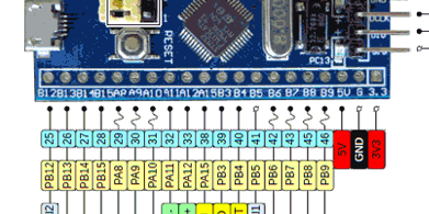
Trying to run Arduino on a STM32F405RGT6 based board [SOLVED]

Hi I am trying to use PlatformIo to use a development board based on STM32F405RGT6 with Arduino framework.
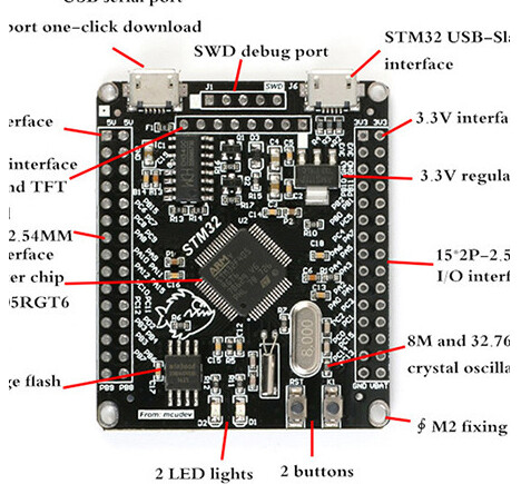
Captura de pantalla 2021-02-07 a las 0.00.20

Everything seems to work perfectly, compile and flash without giving any kind of error message but the board does not seem to be executing the code.

Has anyone found themselves in a similar situation and knows how I can solve it?


This is my platform.ini file:


[env:genericSTM32F405RG]
platform = ststm32
board = genericSTM32F405RG
framework = arduino
upload_protocol = stlink
monitor_speed = 115200

And this is the output console when flashing:


Processing genericSTM32F405RG (platform: ststm32; board: genericSTM32F405RG; framework: arduino)
Verbose mode can be enabled via `-v, --verbose` option
CONFIGURATION: https//docs.platformio.org/page/boards/ststm32/genericSTM32F405RG.html
PLATFORM: ST STM32 (11.0.0) > STM32F405RG (128k RAM. 1024k Flash)
HARDWARE: STM32F405RG 168MHz, 128KB RAM, 1MB Flash
DEBUG: Current (blackmagic) External (blackmagic, jlink, stlink)
PACKAGES: 
 - framework-arduinoststm32 4.10900.200819 (1.9.0) 
 - framework-cmsis 2.50501.200527 (5.5.1) 
 - tool-dfuutil 1.9.200310 
 - tool-openocd 2.1000.200630 (10.0) 
 - tool-stm32duino 1.0.1 
 - toolchain-gccarmnoneeabi 1.90201.191206 (9.2.1)
LDF: Library Dependency Finder -> http://bit.ly/configure-pio-ldf
LDF Modes: Finder ~ chain, Compatibility ~ soft
Found 10 compatible libraries
Scanning dependencies...
No dependencies
Building in release mode
Checking size .pio/build/genericSTM32F405RG/firmware.elf
Advanced Memory Usage is available via "PlatformIO Home > Project Inspect"
RAM:   [          ]   0.7% (used 940 bytes from 131072 bytes)
Flash: [          ]   1.2% (used 12148 bytes from 1048576 bytes)
Configuring upload protocol...
AVAILABLE: blackmagic, dfu, jlink, serial, stlink
CURRENT: upload_protocol = stlink
Uploading .pio/build/genericSTM32F405RG/firmware.elf
xPack OpenOCD, x86_64 Open On-Chip Debugger 0.10.0+dev-00378-ge5be992df (2020-06-26-12:31)
Licensed under GNU GPL v2
For bug reports, read
        http//openocd.org/doc/doxygen/bugs.html
debug_level: 1

hla_swd
target halted due to debug-request, current mode: Thread 
xPSR: 0x01000000 pc: 0x080009c4 msp: 0x20020000
** Programming Started **
** Programming Finished **
** Verify Started **
** Verified OK **
** Resetting Target **
shutdown command invoked
======= [SUCCESS] Took 4.11 seconds ======= 

As as previously stated it seems that compels and upload without any problem but the board does not do anything.

PS: I discard any issue at hardware level since this board works perfectly well when i use it with CubeIDE.
What sketch are you uploading the board?

Have you tried adding

build_flags = -D HSE_VALUE=8000000

to your platformio.ini to make double-sure that the clock-init code works from a 8MHz config?

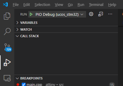
Since you are uploading via an STLink you can also start debugging and see where the board might be stuck. See docs. In VSCode, see

grafik

Also sidenote: The Arduino variant that’s being used when doing board = genericSTM32F405RG is Arduino_Core_STM32/variants/Generic_F4x5RG at 1.9.0 · stm32duino/Arduino_Core_STM32 · GitHub and it has pin defines for default serial pins etc.

1 Like

Hi @maxgerhardt.

Thanks for your answer :slight_smile:

This is my sketch. Very simple, just toggling a pin to verify that the sketch is it working. I connect an oscilloscope to PC13 … but nothing happens.

main.cpp:

#include <Arduino.h>
void setup() {
    pinMode(PC_13,OUTPUT);

}
void loop() {
  // put your main code here, to run repeatedly:
  digitalWrite(PC_13, LOW);
  delay(2);
  digitalWrite(PC_13, HIGH);
  delay(2);
}

As you suggested I added build_flags to platformio.ini :

[env:genericSTM32F405RG]
platform = ststm32
board = genericSTM32F405RG
framework = arduino
upload_protocol = stlink
monitor_speed = 115200
build_flags = 
    -D HSE_VALUE=8000000

It seems that It does not change anything, I will see if I am able to debug to see what may be happening. Do you have any additional suggestions I would try?

Thank you again for your answer.

Regards

You’re using the API wrong.

PC13 is the macro that is accepted by the pinMode fuctions, not PC_13, that is the PinName enum (that can be used with digitalWriteFast btw). There’s a pin-remapping in place in the Arduino core.

See

and

and

and

Hi @maxgerhardt,

I also tried with PC13 instead of PC_13 but is does not make any difference ;(

And you did change it in digitalWrite too?

Yes, I tried:

#include <Arduino.h>
void setup() {
    pinMode(PC13,OUTPUT);

}
void loop() {
  // put your main code here, to run repeatedly:
  digitalWrite(PC13, LOW);
  delay(2);
  digitalWrite(PC13, HIGH);
  delay(2);
}

and this option too :

#include <Arduino.h>
void setup() {
    pinMode(PC_13,OUTPUT);

}
void loop() {
  // put your main code here, to run repeatedly:
  digitalWrite(PC_13, LOW);
  delay(2);
  digitalWrite(PC_13, HIGH);
  delay(2);
}

It makes no difference

The first variant should be correct.

If nothing is happening you should a debugging session as indicated above and see if it’s stuck somewhere / reaches the setup/loop or does whatever.

Hi @maxgerhardt,

I finally got a solution from another forum. Do not know is is a solution or a workaround but it woks :slight_smile: I pos it hear just in case anyone else has the same issue and can take profit from it:


platformio.ini:

[env:genericSTM32F405RG]
platform = ststm32
board = genericSTM32F405RG
board_build.f_cpu = 100000000L
framework = arduino

debug_tool = stlink
upload_protocol = stlink
build_flags =
    -D HSE_VALUE=8000000

monitor_speed = 115200

Yo need CubeIDE to generate SystemClock_Config() with your desired configuration and the cpp it from there and past it before any other function. In my case I has and HSE of 8Mhz and configured to wok with MCU at 100Mhz.

#include <Arduino.h>
#include <SimpleFOC.h>

void SystemClock_Config(void)
{
  RCC_OscInitTypeDef RCC_OscInitStruct = {0};
  RCC_ClkInitTypeDef RCC_ClkInitStruct = {0};

  /** Configure the main internal regulator output voltage
  */
  __HAL_RCC_PWR_CLK_ENABLE();
  __HAL_PWR_VOLTAGESCALING_CONFIG(PWR_REGULATOR_VOLTAGE_SCALE1);
  /** Initializes the RCC Oscillators according to the specified parameters
  * in the RCC_OscInitTypeDef structure.
  */
  RCC_OscInitStruct.OscillatorType = RCC_OSCILLATORTYPE_HSI;
  RCC_OscInitStruct.HSIState = RCC_HSI_ON;
  RCC_OscInitStruct.HSICalibrationValue = RCC_HSICALIBRATION_DEFAULT;
  RCC_OscInitStruct.PLL.PLLState = RCC_PLL_ON;
  RCC_OscInitStruct.PLL.PLLSource = RCC_PLLSOURCE_HSI;
  RCC_OscInitStruct.PLL.PLLM = 8;
  RCC_OscInitStruct.PLL.PLLN = 100;
  RCC_OscInitStruct.PLL.PLLP = RCC_PLLP_DIV2;
  RCC_OscInitStruct.PLL.PLLQ = 4;
  if (HAL_RCC_OscConfig(&RCC_OscInitStruct) != HAL_OK)
  {
    Error_Handler();
  }
  /** Initializes the CPU, AHB and APB buses clocks
  */
  RCC_ClkInitStruct.ClockType = RCC_CLOCKTYPE_HCLK|RCC_CLOCKTYPE_SYSCLK
                              |RCC_CLOCKTYPE_PCLK1|RCC_CLOCKTYPE_PCLK2;
  RCC_ClkInitStruct.SYSCLKSource = RCC_SYSCLKSOURCE_PLLCLK;
  RCC_ClkInitStruct.AHBCLKDivider = RCC_SYSCLK_DIV1;
  RCC_ClkInitStruct.APB1CLKDivider = RCC_HCLK_DIV4;
  RCC_ClkInitStruct.APB2CLKDivider = RCC_HCLK_DIV2;

  if (HAL_RCC_ClockConfig(&RCC_ClkInitStruct, FLASH_LATENCY_3) != HAL_OK)
  {
    Error_Handler();
  }
}


void setup() {
    pinMode(PC13,OUTPUT);

}
void loop() {
  // put your main code here, to run repeatedly:
  digitalWrite(PC13, LOW);
  delay(2);
  digitalWrite(PC13, HIGH);
  delay(2);
}

Go not know if there is a cleaner solution but this at least solves the issue.

Thanks you @maxgerhardt for yours answers :slight_smile:

For refernce, the default is board_build.f_cpu = 168000000L (docs).

You’re using the internal HSI instead of the HSE crystal though.

When change the STM32Cube config to first enable HSE in RCC and then use HSE to get to the maximum clock of 168MHz and then put in that clock generation function, does it work then, too?

If you can’t get the board working when trying to use the 8MHz crystal and all previous firmwares did use HSI+PLL instead of HSE+PLL, it might actually indicate HW failure.

Yes you are right, I forgotten to select HSE instead of HSI … but works in both cases.
This is SystemClock_Config after changing from HSI to HSE. Apparently it makes no difference.

void SystemClock_Config(void)
{
  RCC_OscInitTypeDef RCC_OscInitStruct = {0};
  RCC_ClkInitTypeDef RCC_ClkInitStruct = {0};

  /** Configure the main internal regulator output voltage
  */
  __HAL_RCC_PWR_CLK_ENABLE();
  __HAL_PWR_VOLTAGESCALING_CONFIG(PWR_REGULATOR_VOLTAGE_SCALE1);
  /** Initializes the RCC Oscillators according to the specified parameters
  * in the RCC_OscInitTypeDef structure.
  */
  RCC_OscInitStruct.OscillatorType = RCC_OSCILLATORTYPE_HSE;
  RCC_OscInitStruct.HSEState = RCC_HSE_ON;
  RCC_OscInitStruct.PLL.PLLState = RCC_PLL_ON;
  RCC_OscInitStruct.PLL.PLLSource = RCC_PLLSOURCE_HSE;
  RCC_OscInitStruct.PLL.PLLM = 4;
  RCC_OscInitStruct.PLL.PLLN = 100;
  RCC_OscInitStruct.PLL.PLLP = RCC_PLLP_DIV2;
  RCC_OscInitStruct.PLL.PLLQ = 4;
  if (HAL_RCC_OscConfig(&RCC_OscInitStruct) != HAL_OK)
  {
    Error_Handler();
  }
  /** Initializes the CPU, AHB and APB buses clocks
  */
  RCC_ClkInitStruct.ClockType = RCC_CLOCKTYPE_HCLK|RCC_CLOCKTYPE_SYSCLK
                              |RCC_CLOCKTYPE_PCLK1|RCC_CLOCKTYPE_PCLK2;
  RCC_ClkInitStruct.SYSCLKSource = RCC_SYSCLKSOURCE_PLLCLK;
  RCC_ClkInitStruct.AHBCLKDivider = RCC_SYSCLK_DIV1;
  RCC_ClkInitStruct.APB1CLKDivider = RCC_HCLK_DIV4;
  RCC_ClkInitStruct.APB2CLKDivider = RCC_HCLK_DIV2;

  if (HAL_RCC_ClockConfig(&RCC_ClkInitStruct, FLASH_LATENCY_3) != HAL_OK)
  {
    Error_Handler();
  }
}

Do you know if anything else is needed to be done to have access to SPI, I2C or UART peripherals with this board?

I’m quite a newbie at using boards, let’s say “unconventional” boards, and I’m still learning.

Regards.

It’s intersting then how the default doesn’t work… the clock setup in the the used Arduino variant

Yes they’re using a dfferent set of multipliers and dividers but with HSE_VALUE = 8000000 it still works out to rated max speed of 8000000 [Hz] / 8 * 336 / 2 = 168 MHz.

But okay, if HSE+PLL works with 100MHz and board_build.f_cpu is updated it should be okay. Still not max-speed though.

Not that I know of – the generic variant has all pins exposed / accessible with the PA0…PH1 macros. UART by default is on

but you can also enable the other UARTS by adding -D HAVE_HWSERIALX macros to the build_flags, as seen in the source.

The main object for the I2C transfers (TwoWire from the Wire) library has a constructor where you can pass in the I2C pins you want to use.

The default pins will be whatever the 14th and 15th pins is, since the variant.h doesn’t define the default macro.

so that would be

in this case for SDA and SCL.

EDIT: Which is really bad, since PA_14/15 isn’t I2C capable / connected to the I2C peripheral.

So you should be instantiating with something like PB6 and PB7 manually or use a -D PIN_WIRE_SDA=PB7 -D PIN_WIRE_SCL=PB6 in the build_flags.

SPI is similiar, see code.

More than a modified clock config for the board shouldn’t be necessary, all other things should just work, given the code is given the right pinnames / macros.

1 Like

Hi @maxgerhardt your recipes worked wonderfully :slight_smile: Sorry for the late answer. By the way do you know if any in order to have PWMs pins any further compilation flag is needed ?


Captura de pantalla 2021-02-08 a las 23.40.32


In Blue Pill Board such pins are tagged with a differentiated symbol (PA8, PA9, Pa10, …) and I do not know if I have to do something in order to have such capabilities.

Best regards !!!

PWM capable pins and the timers (and timer channels) they use are listed in the variant.cpp.

Note that each pin can generate a PWM signal based from different timers and configs (like PA_0 could do it from TIM2_CH2, or TIM5_CH1 or TIM5_CH2), but only one of them is activated, so the devs have made that choice for you already. If you need to take control of that you’d need to create your own variant (example: GitHub - maxgerhardt/pio-custom-stm32duino-variants: A short example of how to use a custom variant folder for the PlatformIO + STM32Duino environment), otherwise they should just be ready to go.

The available APIs would be the Arduino core’s analogWrite(), with the STM32Duino core additionally having analogWriteFrequency() (docs).

For low-level control, the HardwareTimer library may also be used.

1 Like

Thanks for you response @maxgerhardt :slight_smile: I will try your recipie for PWM as soon as receive a BLDC driver that is coming from china :slight_smile:

Regards!!