Hi All,
Does anyone know if the chipset is stm32G031C8, which target MCU should I choose in platformIO?
Thanks.
Nathan Kuo
Hi All,
Does anyone know if the chipset is stm32G031C8, which target MCU should I choose in platformIO?
Thanks.
Nathan Kuo
The board isn’t directly supported yet. But you can create your own board definition file.
C:\Users\you\.platformio\platforms\ststm32\boards\disco_g031j6.json to C:\Users\you\.platformio\boards\genericSTMG031C8.json
"platform": "ststm32", on the second lineThen the board should be available in PlatformIO.
Most likely, it will not work with the Arduino framework as it isn’t supported yet by the STM32 Arduino core. But the other frameworks should work.
A close match in the Arduino core would be the STM32G031J6 from the STM32G0316-DISCO board, which is supported in PIO.
You can either try that configuration directly, or work from this board definition. There also an example of creating a custom Arduino-STM32 variant in PlatformIO (GitHub - maxgerhardt/pio-custom-stm32duino-variants: A short example of how to use a custom variant folder for the PlatformIO + STM32Duino environment) and the core has great documentation on how to add support for a new board. Would you feel comfortable trying that?
Thanks for your answer.
But I have more questions.
I don’t know how to create custom variant.cpp and variant.h for STMG031C8 and how to find the pinout define rule on STMG031C8 datasheet.
Can you teach me how to define pin assignment mapping , I can’t find the rules for other sample chipsets.
From the example pio-custom-stm32duino-variants/custom_variants/CUSTOM_NUCLEO_L476RG_VERSION_1 at main · maxgerhardt/pio-custom-stm32duino-variants · GitHub
Why the PC10 is “16” ? Where did you get this number?
Many thanks for your help.
Nathan Kuo
because it is the position “i = 16” in the array / “D16” and PC10 has to match the position of PC_10.
This is also explained in the documentation I’ve linked to.
Let me see if I can write a short example.
I’ve created a test project at GitHub - maxgerhardt/pio-stm32g031c8-support: Board definition and example for STM32Cube and Arduino for the STM32G031C8 MCU in PlatformIO if you want to test it. Supports STM32Cube as a baseline test and also a STM32Duino integration based on the DISCO_G0316.
Compiles, unsure if it runs because I don’t have the chip. Configured for HSI instead of HSE since I didn’t assume you’d have a crystal in board. Pin mapping is unchanged from the DISCO board.
Hi,
But I still don’t understand relationship between position and digital pin.
For example, the position of PA_3 is 0(D0) , PA_2 is 1(D1) … PC_10 is 16(D16) , how do you know this part and it is in the data sheet? I still can’t get it…
In the STMG031C8 data sheet, I don’t know the pin name and number of the first position.
Anyway , thanks for your replay.
Nathan Kuo
This is the variant I created for G031C8 ,
Can you help me see if there is an error?
Generic_G031C8
The positions of the pins can be abitrary. User-chosen. If the actual used PCB has a “Arduino style connector”, such as the bigger Nucleo boards, then it it totally makes sense to map “D0” of the physical conenctor to the actual pin that is connected there to the STM32 MCU.
If there is no such connector then just create any mapping you like, doesn’t matter what “D0” etc. is as long as the mapping is consistent and you can use names like PA3 anyways.
For the STM32G0316-DISCO board, I also don’t see though why this exact pin mapping was choosen since it doesn’t have an Arduino connector. The chip only has 8 legs, see user manual.
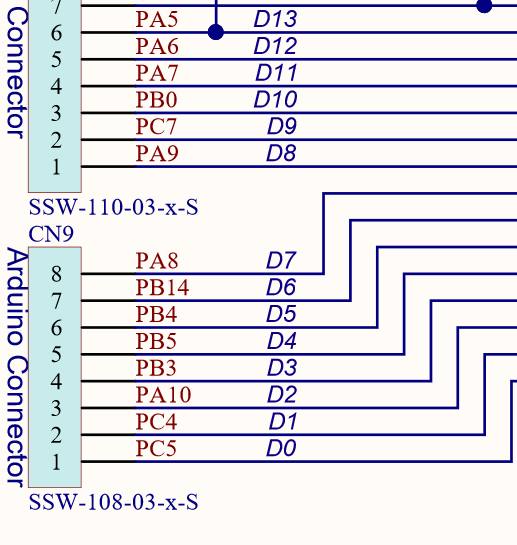
For other implementations like the “Nucleo G071RB” it makes much more sense though. In its schematics you see
And to no surprise…
Thus that makes sense for boards that have the connector.
"maximum_size": 131072 is wrong since I read in the datasheet that the C8 variant has 64kByte flashstlink to the protocols and also made it a default. Without that you can’t flash it with an STLink"openocd_target": "stm32g0x", line in the debug session so that it knows what openOCD config file to usestm32cube is missing in possible frameworks, this compiles as I’ve demonstrated in my repoPeripheralPins.c and PinNamesVar.h are the same since we both source them from the same site, which should be correct according to STM32Duino docsSystemClock_Config() function in your variant.cpp does more than mine. You probably activated the USART1 peripheral in the STM32CubeMX project, if it was generated from there? The UART driver code will already do that. I sticked to the docs here to just initialize the main clocks.variant.cpp and variant.h are missing the analog pin array analogInputPin and macros like NUM_ANALOG_INPUTSIf you wish to use analog pins / the ADC, certain rules in the pin ordering and the macro values must be followed
// If NUM_ANALOG_FIRST is not defined:
// - Ax are not contiguous in the digitalPin array
// - analogInputPin array is available
#ifndef NUM_ANALOG_FIRST
  #define NUM_ANALOG_FIRST          (NUM_DIGITAL_PINS + 1)
  #define NUM_ANALOG_LAST           (NUM_DIGITAL_PINS + NUM_ANALOG_INPUTS)
  #define NUM_ANALOG_INTERNAL_FIRST (NUM_ANALOG_LAST + 1)
#else
  #define NUM_ANALOG_INTERNAL_FIRST (NUM_DIGITAL_PINS + 1)
#endif
LED_BUILTIN definedTIMER_TONE and TIMER_SERVO defined, possibly those libraries and functions won’t work or interfere with somethingThat what I see when I glance over it.
With PlatformIO you also have debugging capilities if you flash via an STLink or any SWD debugger. So you can still try and correct stuff.