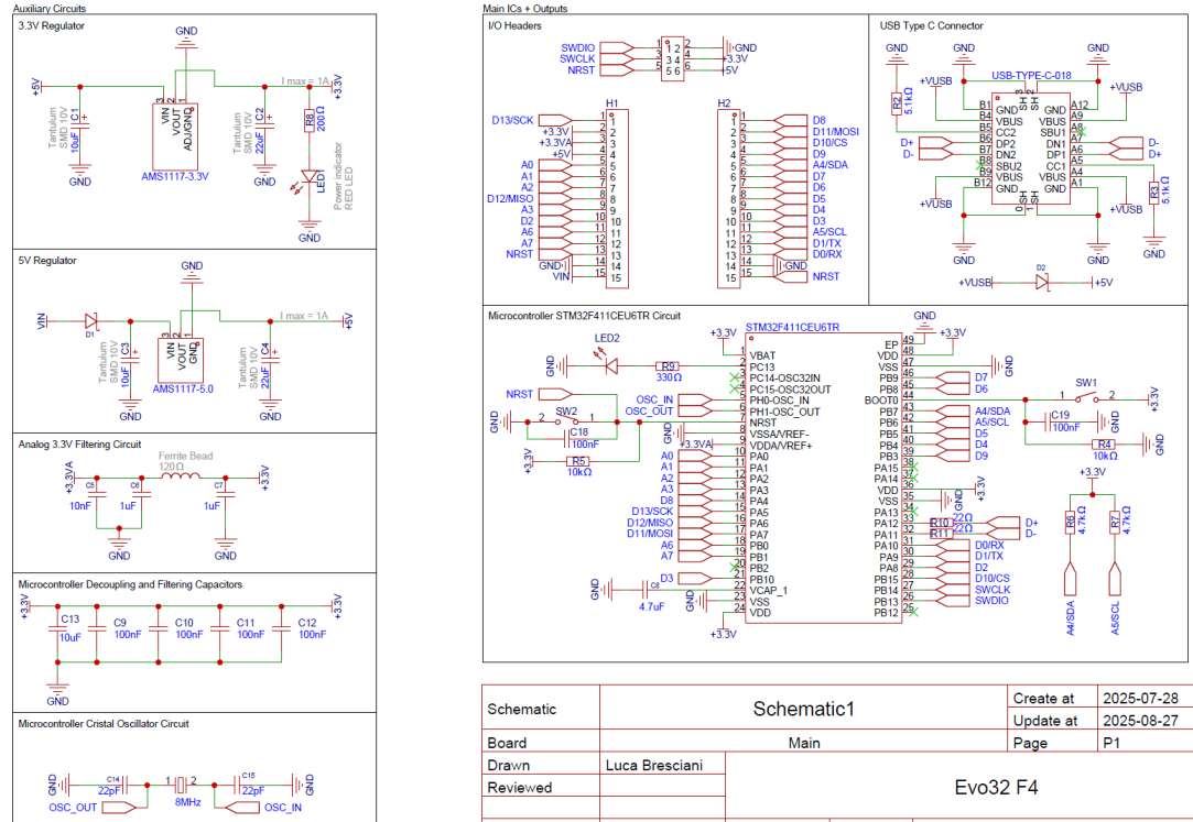
Hi everyone: i received in these days a custom PCB i designed based on the STM32F411 microcontroller:
I wanted to experiment with such MCUs and make a custom board with them for the first time; i was also interested in making it compatible with the arduino framework through PlatformIO as i already have some working pieces of code for arduino that i don’t want to lose.
I started running some tests and it turned out that i was able to program it and to use the serial monitor just fine; however the problems started when i tryed to use I2C sensors like this BME280 Breackout board i got from Amazon: i started simple by connecting it up to 3V3, same GND as the STM32 board, and SDA and SCL according to the attached PCB schematic.
I used this code as a firts test I2C address scanner in the main.c file:
#include <Arduino.h>
#include <Wire.h>

int nDevices = 0;

void setup() {
  delay(1000);

  Wire.begin();

  Serial.begin(115200);
  while(!Serial){
    delay(10);
  }

  pinMode(PC13, OUTPUT);

  Serial.println("I2C pronto!");

  // Scan I2C
  byte error, address;
  for (address = 1; address < 127; address++) {
    Wire.beginTransmission(address);
    error = Wire.endTransmission();
    Serial.println(error);
    if (error == 0) {
      Serial.print("device found at 0x");
      Serial.println(address, HEX);
      nDevices++;
    }
    delay(5);  // Add small delay between attempts
  }
}

void loop() {
  if(nDevices != 0){
    digitalWrite(PC13, !digitalRead(PC13));
    delay(250);
  } else {
    Serial.println("no device found");
    delay(500);
  }
}
I also put this in the platformio.ini file (as u can see i was initially using the “genericSTM32F411CE” board on platformio):
[env:genericSTM32F411CE]
platform = ststm32
board = genericSTM32F411CE
framework = arduino
upload_protocol = dfu
build_flags =
-D PIO_FRAMEWORK_ARDUINO_ENABLE_CDC
-D USBCON
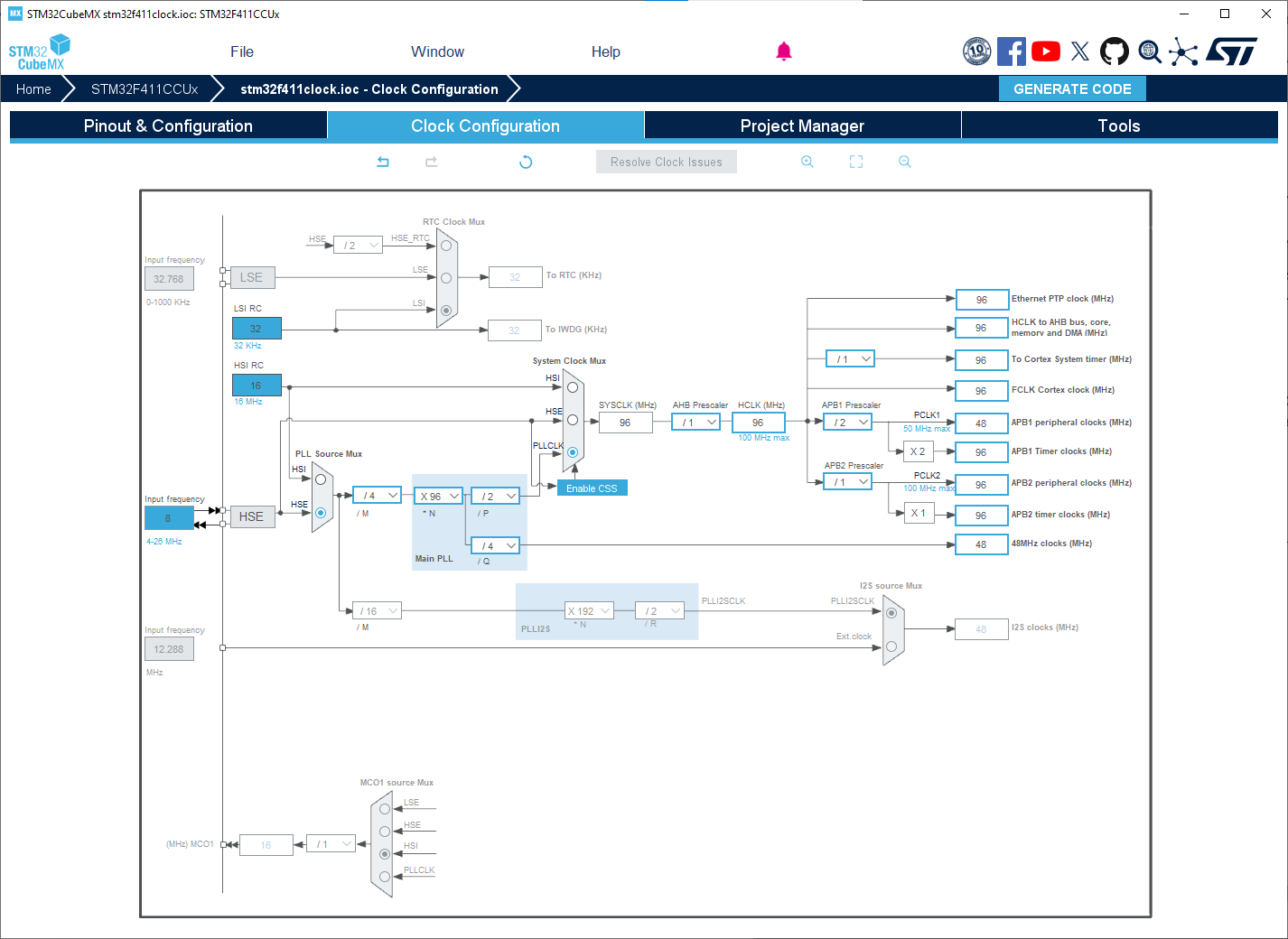
-D HSE_VALUE=8000000
-D ARDUINO_PIN_SDA=PB7
-D ARDUINO_PIN_SCL=PB6
With this setup it wasn’t finding any I2C device but at least it was printing such error message on the serial monitor as the code sayed.
Later i tryed swapping both “board” and “env” in the platformio.ini file with “blackpill_f411ce” and this time something weird happened: soon after startup the board started flashing its LED as it found a device but on the PC (in the device manager tab) it couldn’t recognise the STM32 board and thus not open the serial monitor on Platformio.
I assume it’s something more software related but i wouldn’t exlucde completely some hardware errors due to my inexperience working with STM32. Also i wanna poit out that the sensor breackout board works just fine as i tested it with a separate Arduino nano that powered the sensor with the same 3.3V as my custom PCB; i also verified that the power supply of my pcb that regualtes the 5V of the USB-C down to 3.3V was working and capable of powering both the STM32 and the sensor breackout.
Any help will be apreciated