STM32F103RB comunication SPI

HELLO

how i define the second port/bus of SPI on muc stm32f103???

/Pins of spi 2*************************************
//#define SCS PB1 //1 // SLAVE PIN
//#define MOSI PB15 // MOSI, for “Master Out / Slave In”.
//#define MISO PB14 // MISO, for “Master In / Slave Out”.
//#define SCLK PB13 //clock
//***********************************************************************/

//******* pins of SPI 1**************************************************
//#define SCS PA4 // SLAVE PIN
//#define MOSI PA7 //MOSI, for “Master Out / Slave In”.
//#define MISO PA6 // MISO, for “Master In / Slave Out”.
//#define SCLK PA5 //clock

i use this configuration on platformio.ini

[env:genericSTM32F103RB]
platform = ststm32@5.1.0
board = genericSTM32F103RB
framework = arduino
debug_tool = stlink
upload_protocol = stlink
monitor_speed = 115200
monitor_port = COM9

my two first line of my code have this
#include <Arduino.h>;
#include <SPI.h>;

It looks like on the stm32duino core the pins are defined using the constructor? So something like SPIClass SPI_2(MOSI,MISO,SCLK,SCS); should create a SPI_2 object with the defined pins.

Btw, there shouldn’t be semi-colons ‘;’ after include statements :wink:

Hey,
Did you get this to work? I was trying to use the SPI_2 method as well and the software seemed to crash every time.

We might be able to help you if you post your current platformio.ini and (minimal) code that attempts to create and use SPI2.

Sure thing, thank you for taking the time. The board freezes when I try to begin the 2nd SPI

Blockquote
#define P_MISO PB14
#define P_MOSI PB15
#define P_SCK PB13
#define P_MISO2 PB5
#define P_MOSI2 PB4
#define P_SCK2 PB3
#define P_CS_DN PB12 //PB12
#define P_CS_UP PA7 //PA7
SPIClass SPI_2(P_MISO2,P_MOSI2,P_SCK2,P_CS_UP);

SPI.setMISO(P_MISO);
SPI.setMOSI(P_MOSI);
SPI.setSCLK(P_SCK);
_cs = P_CS_DN;

pinMode(P_CS_DN, OUTPUT);
pinMode(P_CS_UP, OUTPUT);
digitalWrite(P_CS_DN, HIGH);
digitalWrite(P_CS_UP, HIGH);

SPI.begin(); 
SPI.beginTransaction(SPISettings(1000000, MSBFIRST, SPI_MODE3));
// Make sure the SPI bus is reset
digitalWrite(P_CS_DN, HIGH);
delay(1);
digitalWrite(P_CS_DN, LOW);
delay(1);
digitalWrite(P_CS_DN, HIGH);
delay(1);
SPI.endTransaction();

delay(5);
SPI_2.begin();  // <<<<<<<<<<<<<<<<<<<<<<<< THIS IS WHERE IT FAILS
SPI_2.beginTransaction(SPISettings(1000000, MSBFIRST, SPI_MODE3));
// Make sure the SPI bus is reset
digitalWrite(P_CS_UP, HIGH);
delay(1);
digitalWrite(P_CS_UP, LOW);
delay(1);
digitalWrite(P_CS_UP, HIGH);
delay(1);
SPI_2.endTransaction();

platorm.ini:

Blockquote
[env:dalek_1_3]
platform = ststm32@5.7
board = bluepill_f103c8_128k
framework = arduino
upload_port = /dev/ttyUSB*
upload_protocol = serial
monitor_speed = 115200
lib_extra_dirs = …/libs
build_flags = -DDALEK_1_3 -O3 ; COMMENT THIS FOR MANUAL FLIGHT ON DALEK 1_3

This is ancient – the current version is 14.2.0. If you don’t have a strong reason against it you should be using the latest platform version, and with it comes the latest Arduino STM32 core (2.0.0). You might be seeing bugs that have been fixed in the core years ago in your firmware.

Hm, this doesn’t look right. Referencing against the pinout of the Bluepill / STM32F103C8 here shows

  • SPI1:
    • MOSI = PB5
    • MISO = PB4
    • SCLK = PB3
  • SPI2:
    • MOSI = PB15
    • MISO = PB14
    • SCLK = PB13

So if the #define P_MISO PB14 is supposed to be for SPI1, which it looks like because you use P_MISO2 etc in the SPI_2 creation, that’s wrong (SPI1 and SPI2 confused). Also, you’ve confused MOSI with MISO (in your code P_MISO2 is PB5 when SPI1_MISO is actually PB4). The latter means you’re most likely crashing at the peripheral pin check.

Also you you shouldn’t give the instantiated SPI object the chip-select pin, because otherwise it’ll assume thaht’s a hardware NSS pin. (Refer here, here and here).

If I test the following code on my bluepill

#include <Arduino.h>
#include <SPI.h>

/* SPI1 pin defs */
#define P_MISO PB4
#define P_MOSI PB5
#define P_SCK PB3
/* SPI2 pin defs */
#define P_MOSI2 PB15
#define P_MISO2 PB14
#define P_SCK2 PB13
/* chip select definitions */
#define P_CS_DN PB12 //PB12
#define P_CS_UP PA7  //PA7

SPIClass SPI_2(P_MISO2, P_MOSI2, P_SCK2);

void setup()
{
  Serial.begin(115200);
}

void loop()
{
  SPI.setMISO(P_MISO);
  SPI.setMOSI(P_MOSI);
  SPI.setSCLK(P_SCK);
  int _cs = P_CS_DN;

  pinMode(P_CS_DN, OUTPUT);
  pinMode(P_CS_UP, OUTPUT);
  digitalWrite(P_CS_DN, HIGH);
  digitalWrite(P_CS_UP, HIGH);

  Serial.println("SPI(1).begin() start");
  SPI.begin();
  Serial.println("SPI(1).begin() done");
  SPI.beginTransaction(SPISettings(1000000, MSBFIRST, SPI_MODE3));
  // Make sure the SPI bus is reset
  digitalWrite(P_CS_DN, HIGH);
  delay(1);
  digitalWrite(P_CS_DN, LOW);
  delay(1);
  digitalWrite(P_CS_DN, HIGH);
  delay(1);
  SPI.endTransaction();

  Serial.println("SPI(1) transaction done");
  delay(5);
  Serial.println("SPI_2.begin() start");
  SPI_2.begin(); // <<<<<<<<<<<<<<<<<<<<<<<< THIS IS WHERE IT FAILS
  Serial.println("SPI_2.begin() end");
  SPI_2.beginTransaction(SPISettings(1000000, MSBFIRST, SPI_MODE3));
  // Make sure the SPI bus is reset
  digitalWrite(P_CS_UP, HIGH);
  delay(1);
  digitalWrite(P_CS_UP, LOW);
  delay(1);
  digitalWrite(P_CS_UP, HIGH);
  delay(1);
  SPI_2.endTransaction();
  Serial.println("SPI(2) transaction done");
  delay(500);
}

with the platformio.ini

[env:dalek_1_3]
platform = ststm32
board = bluepill_f103c8_128k
framework = arduino
monitor_speed = 115200

I get…

--- Miniterm on COM3  115200,8,N,1 ---
--- Quit: Ctrl+C | Menu: Ctrl+T | Help: Ctrl+T followed by Ctrl+H ---
SPI(1).begin() start
SPI(1).begin() done
SPI(1) transaction done
SPI_2.begin() start
SPI_2.begin() end
SPI(2) transaction done
SPI(1).begin() start
SPI(1).begin() done
SPI(1) transaction done
SPI_2.begin() start
SPI_2.begin() end
SPI(2) transaction done

no crash.

Hi Max,
Thank you for your feedback.
I have updated to the latest core version (There used to be an issue with compilation at version 6.1).
And switched the MOSI MISO which were indeed wrong.
It seems now that the begin and end transactions are successful but when I try to transfer data to the system its crashes.
I have tried running your code with the following change at the end of the loop. Any idea what I am doing wrong? I am guessing it fails at the data transfer but I don;t really understand why.

  uint8_t reg,value;
  Serial.println("Sending data Completed");
  Serial.println("SPI(1) data transfer begin");
  SPI.beginTransaction(SPISettings(1000000, MSBFIRST, SPI_MODE3));
   reg = 0x00;
  reg &= ~0x80u;
  digitalWrite(P_CS_DN, LOW);
  delayMicroseconds(5);
  SPI.transfer(reg);
  delayMicroseconds(5);
  value = SPI.transfer(0);
  delayMicroseconds(20);
  digitalWrite(P_CS_DN, HIGH);
  SPI.endTransaction();
  Serial.println("SPI(1) data transfer end");
  delay(500);
  Serial.println("SPI(2) data transfer begin");
  delay(200);
  SPI_2.beginTransaction(SPISettings(1000000, MSBFIRST, SPI_MODE3));
  reg = 0x00;
  reg &= ~0x80u;
  digitalWrite(P_CS_UP, LOW);
  delayMicroseconds(5);
  SPI_2.transfer(reg);
  delayMicroseconds(5);
  value = SPI_2.transfer(0);
  delayMicroseconds(20);
  digitalWrite(P_CS_UP, HIGH);
  SPI_2.endTransaction();
  Serial.println("SPI(2) data transfer end");
  delay(500);

That’s my serial output:

SPI(1).begin() start
SPI(1).begin() done
SPI(1) transaction done
SPI_2.begin() start
SPI_2.begin() end
SPI(2) transaction done
Sending data Completed
SPI(1) data transfer begin
SPI(1) data transfer end
SPI(2) data transfer begin

Interesting, I see the same: The code is waiting for the SPI transaction to be completed.

I’ll see why that is. Maybe it internally has the wrong SPI peripheral or some interrupt handler is not called.

EDIT: Yes the problem is apparent, _SPI is nullptr, the SPI object is not initialized correctly…

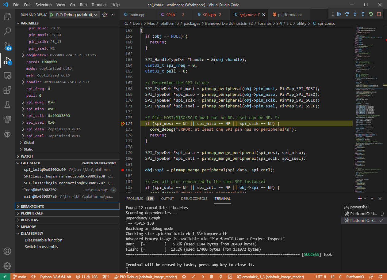
The MISO/MOSI pins for SPI2 are still incorrect. It can’t find the peripheral (SPI2) associated with MISO/MOSI and is thus not doing the internal initialization (setting obj->spi).

I might have made a mistake, or Arduino’s pinmaps are wrong. Let me check again.

Ouch, of course:

/* SPI2 pin defs */
#define P_MOSI2 PB15
#define P_MISO2 PB14
#define P_SCK2 PB13
/* chip select definitions */
#define P_CS_DN PB12 //PB12
#define P_CS_UP PA7  //PA7

SPIClass SPI_2(P_MISO2, P_MOSI2, P_SCK2);

the SPIClass constructor takes

    SPIClass(uint8_t mosi, uint8_t miso, uint8_t sclk, uint8_t ssel = (uint8_t)NC);

Aka, MOSI + MISO, not MOSI + MISO. The errors in the pin definitions with switching them and the constructor call here actually canceled out previously in your example.

Here is how it has to be in the correct form:

#include <Arduino.h>
#include <SPI.h>

/* SPI1 pin defs */
#define P_MISO PB4
#define P_MOSI PB5
#define P_SCK PB3
/* SPI2 pin defs */
#define P_MOSI2 PB15
#define P_MISO2 PB14
#define P_SCK2 PB13
/* chip select definitions */
#define P_CS_DN PB12 //PB12
#define P_CS_UP PA7  //PA7

SPIClass SPI_2(P_MOSI2, P_MISO2, P_SCK2);

void setup()
{
  Serial.begin(115200);
}

void loop()
{
  SPI.setMISO(P_MISO);
  SPI.setMOSI(P_MOSI);
  SPI.setSCLK(P_SCK);
  int _cs = P_CS_DN;

  pinMode(P_CS_DN, OUTPUT);
  pinMode(P_CS_UP, OUTPUT);
  digitalWrite(P_CS_DN, HIGH);
  digitalWrite(P_CS_UP, HIGH);

  //SPI.begin();
  //SPI_2.begin();

  uint8_t reg,value;
  Serial.println("Sending data Completed");
  Serial.println("SPI(1) data transfer begin");
  SPI.beginTransaction(SPISettings(1000000, MSBFIRST, SPI_MODE3));
   reg = 0x00;
  reg &= ~0x80u;
  digitalWrite(P_CS_DN, LOW);
  delayMicroseconds(5);
  SPI.transfer(reg);
  delayMicroseconds(5);
  value = SPI.transfer(0);
  delayMicroseconds(20);
  digitalWrite(P_CS_DN, HIGH);
  SPI.endTransaction();
  Serial.println("SPI(1) data transfer end");
  delay(500);
  Serial.println("SPI(2) data transfer begin");
  delay(200);
  SPI_2.beginTransaction(SPISettings(1000000, MSBFIRST, SPI_MODE3));
  reg = 0x00;
  reg &= ~0x80u;
  digitalWrite(P_CS_UP, LOW);
  delayMicroseconds(5);
  SPI_2.transfer(reg);
  delayMicroseconds(5);
  value = SPI_2.transfer(0);
  delayMicroseconds(20);
  digitalWrite(P_CS_UP, HIGH);
  SPI_2.endTransaction();
  Serial.println("SPI(2) data transfer end");
  delay(500);
}