STM32F103CB UART3 at 2Mbps

Hello,

I have a custom board with an STM32F103CB and I use UART3 for serial communication. I can configure the port and successfully exchanged messages with the master at 9600bps, 115200bps and 100000bps. When trying to configure the UART at 2000000bps, while there seems to be no problem with the configuration, the communication is no longer working.

The platform.io:

[env:prodSTM32F103CB]
platform = ststm32
board = genericSTM32F103CB
framework = arduino
lib_deps = robotis-git/Dynamixel2Arduino
build_flags = 
	-D ENABLE_HWSERIAL3
	-D ADC_SAMPLINGTIME=ADC_SAMPLETIME_28CYCLES_5
	-D USE_HSE_CLOCK
	-D HSE_VALUE=8000000UL

upload_protocol = stlink
debug_tool = stlink
debug_server = 
	/Users/Alex/.platformio/packages/tool-openocd/bin/openocd
	-s /Users/Alex/.platformio/packages/tool-openocd/scripts
	-f interface/stlink.cfg
	-c "transport select hla_swd"
	-f target/stm32f1x.cfg
	-c "reset_config none"

I have debugged the USART3 peripheral and here are the values for the BRR register:

speed       BRR       Mantissa    Fraction   USARTDIV
57600       0x22C     0x22        0xC        34.75
115200      0x116     0x11        0x6        17.375
1000000     0x20      0x2         0x0        2.0
2000000     0x10      0x1         0x0        1.0

The PCLK1 seems to be thus 32Mhz.

I would appreciate any suggestions.

Thanks.

Per

that gives you that variant, but I’m pretty sure with the generic_clock.c file…

Which, since no USB is enabled in your firmware, will follow the lower codepath, which sets up HSI (8MHz) dividided by 2 with the PLL of factor 16, so a total of 8*8 = 64MHz.

There are 0 results for this in the STM32Duino code.

https://github.com/stm32duino/Arduino_Core_STM32/search?q=USE_HSE_CLOCK

So this has no effect. You would need to add a function in your firmware code that defines void SystemClock_Config(void) with the settings you want. For example, in any src/xxxx.cpp file,

#include <Arduino.h>

extern "C" void SystemClock_Config(void)
{
  RCC_OscInitTypeDef RCC_OscInitStruct = {};
  RCC_ClkInitTypeDef RCC_ClkInitStruct = {};
  RCC_PeriphCLKInitTypeDef PeriphClkInit = {};

  /* Initializes the CPU, AHB and APB busses clocks */
  RCC_OscInitStruct.OscillatorType = RCC_OSCILLATORTYPE_HSE;
  RCC_OscInitStruct.HSEState = RCC_HSE_ON;
  RCC_OscInitStruct.HSEPredivValue = RCC_HSE_PREDIV_DIV1;
  RCC_OscInitStruct.HSIState = RCC_HSI_ON;
  RCC_OscInitStruct.PLL.PLLState = RCC_PLL_ON;
  RCC_OscInitStruct.PLL.PLLSource = RCC_PLLSOURCE_HSE;
  RCC_OscInitStruct.PLL.PLLMUL = RCC_PLL_MUL9;
  if (HAL_RCC_OscConfig(&RCC_OscInitStruct) != HAL_OK) {
    Error_Handler();
  }

  /* Initializes the CPU, AHB and APB busses clocks */
  RCC_ClkInitStruct.ClockType = RCC_CLOCKTYPE_HCLK | RCC_CLOCKTYPE_SYSCLK
                                | RCC_CLOCKTYPE_PCLK1 | RCC_CLOCKTYPE_PCLK2;
  RCC_ClkInitStruct.SYSCLKSource = RCC_SYSCLKSOURCE_PLLCLK;
  RCC_ClkInitStruct.AHBCLKDivider = RCC_SYSCLK_DIV1;
  RCC_ClkInitStruct.APB1CLKDivider = RCC_HCLK_DIV2;
  RCC_ClkInitStruct.APB2CLKDivider = RCC_HCLK_DIV1;

  if (HAL_RCC_ClockConfig(&RCC_ClkInitStruct, FLASH_LATENCY_2) != HAL_OK) {
    Error_Handler();
  }

  PeriphClkInit.PeriphClockSelection = RCC_PERIPHCLK_ADC | RCC_PERIPHCLK_USB;
  PeriphClkInit.AdcClockSelection = RCC_ADCPCLK2_DIV6;
  PeriphClkInit.UsbClockSelection = RCC_USBCLKSOURCE_PLL_DIV1_5;
  if (HAL_RCCEx_PeriphCLKConfig(&PeriphClkInit) != HAL_OK) {
    Error_Handler();
  }
}

would actually enable the HSE with factor 9, giving the full 8*9 = 72MHz.

Does adding that already make a difference?

Thank you for the very fast response.

When debugging with the additional SystemClock_Config I do se the following changes:

  • The RCC_CR register now shows HSEON=0b1 and HSERDY=0b1 while previously were 0 (the activation of HSE)
  • The BRR register on UART3 now show divisors that indicate the PCLK1 is 36Mhz (ex for 1000000 the BRR is 0x24 so mantissa is 0x2 and fraction is 0x4 producing a USARTDIV=2.25 consistent with a 36Mhz PCLK1)

Unfortunately the communication is still not working at 2Mbps, but continues to work at other lower speeds. I have tested the master with other peripherals at 2Mbps and that seems to be fine, so there is not a fault in the master.

Do you have a logic analyzer or oscilloscope available to you that can reasonably sample a 2MHz signal? Just to do some basic checks whether a transmit signal is present at all and what the real bit timings are.

Max, I do have one and I will try to do that. The problem is that the device is a slave that is listening to the serial port and responding - but I can make a spearate script just to test that.

I am pretty sure that I had previously an .ino script in Arduino IDE using stm32duino that worked at 2Mbps with the bluepill on the same UART3. I will dig out the bin try to flash it to see if that still works and will report back.

Thanks for the help.

Alex.

1 Like

@maxgerhardt sorry for taking this into a different direction, but trying to work on the serial issue I have bricked the chip.

I tried to load an older bin with:

st-flash --reset write old_bin_filename.bin 0x8000000

and after that I cannot do anything with the board.

Now if I do an upload from VCode from Platformio I get this (in verbose mode):

> Executing task: platformio run --verbose --target upload --environment prodSTM32F103CB <

Processing prodSTM32F103CB (platform: ststm32; board: genericSTM32F103CB; framework: arduino; lib_deps: robotis-git/Dynamixel2Arduino; build_flags: -D ENABLE_HWSERIAL3, -D ADC_SAMPLINGTIME=ADC_SAMPLETIME_28CYCLES_5, -D HSE_VALUE=8000000UL; upload_protocol: stlink; debug_tool: stlink; debug_server: /Users/Alex/.platformio/packages/tool-openocd/bin/openocd, -s /Users/Alex/.platformio/packages/tool-openocd/scripts, -f interface/stlink.cfg, -c "transport select hla_swd", -f target/stm32f1x.cfg, -c "reset_config none")
--------------------------------------------------------------------------------------------------------------------------------------------------------------------------------------------------------------------------
CONFIGURATION: https://docs.platformio.org/page/boards/ststm32/genericSTM32F103CB.html
PLATFORM: ST STM32 (15.1.0) > STM32F103CB (20k RAM. 128k Flash)
HARDWARE: STM32F103CBT6 72MHz, 20KB RAM, 128KB Flash
DEBUG: Current (stlink) External (blackmagic, cmsis-dap, jlink, stlink)
PACKAGES: 
 - framework-arduinoststm32 4.20100.211028 (2.1.0) 
 - framework-cmsis 2.50700.210515 (5.7.0) 
 - tool-dfuutil 1.9.200310 
 - tool-openocd 2.1100.211028 (11.0) 
 - tool-stm32duino 1.0.1 
 - toolchain-gccarmnoneeabi 1.90201.191206 (9.2.1)
LDF: Library Dependency Finder -> https://bit.ly/configure-pio-ldf
LDF Modes: Finder ~ chain, Compatibility ~ soft
Found 12 compatible libraries
Scanning dependencies...
Dependency Graph
|-- <Dynamixel2Arduino> 0.5.3 (/Users/Alex/Documents/Electronics/KiCad Projects/SPR2010-MH5_FSR/firmware/.pio/libdeps/prodSTM32F103CB/Dynamixel2Arduino)
|-- <EEPROM> 2.0.1 (/Users/Alex/.platformio/packages/framework-arduinoststm32/libraries/EEPROM)
Building in release mode
MethodWrapper(["checkprogsize"], [".pio/build/prodSTM32F103CB/firmware.elf"])
Advanced Memory Usage is available via "PlatformIO Home > Project Inspect"
RAM:   [=         ]  14.9% (used 3048 bytes from 20480 bytes)
Flash: [==        ]  19.3% (used 25324 bytes from 131072 bytes)
.pio/build/prodSTM32F103CB/firmware.elf  :
section              size        addr
.isr_vector           268   134217728
.text               22520   134217996
.rodata              2500   134240516
.ARM.extab              0   134243016
.ARM                    0   134243016
.preinit_array          0   134243016
.init_array            20   134243016
.fini_array             8   134243036
.data                 304   536870912
.bss                 2744   536871216
.noinit                 0   536873960
._user_heap_stack    1536   536873960
.ARM.attributes        41           0
.comment              102           0
.debug_frame         1464           0
Total               31507
<lambda>(["upload"], [".pio/build/prodSTM32F103CB/firmware.elf"])
AVAILABLE: blackmagic, cmsis-dap, dfu, jlink, serial, stlink
CURRENT: upload_protocol = stlink
openocd -d2 -s /Users/Alex/.platformio/packages/tool-openocd/scripts -f interface/stlink.cfg -c "transport select hla_swd" -f target/stm32f1x.cfg -c "program {.pio/build/prodSTM32F103CB/firmware.elf}  verify reset; shutdown;"
xPack OpenOCD x86_64 Open On-Chip Debugger 0.11.0+dev (2021-10-17-00:18)
Licensed under GNU GPL v2
For bug reports, read
        http://openocd.org/doc/doxygen/bugs.html
debug_level: 2

hla_swd
Info : The selected transport took over low-level target control. The results might differ compared to plain JTAG/SWD
Info : DEPRECATED target event trace-config; use TPIU events {pre,post}-{enable,disable}
Info : clock speed 1000 kHz
Info : STLINK V2J37S7 (API v2) VID:PID 0483:3748
Info : Target voltage: 3.185799
Warn : target stm32f1x.cpu examination failed
Info : starting gdb server for stm32f1x.cpu on 3333
Info : Listening on port 3333 for gdb connections
embedded:startup.tcl:1070: Error: ** Unable to reset target **
in procedure 'program' 
in procedure 'program_error' called at file "embedded:startup.tcl", line 1107
at file "embedded:startup.tcl", line 1070
*** [upload] Error 1
=============================================================================================== [FAILED] Took 2.69 seconds ===============================================================================================

Environment       Status    Duration
----------------  --------  ------------
cloneSTM32F103CB  IGNORED
prodSTM32F103CB   FAILED    00:00:02.687
========================================================================================= 1 failed, 0 succeeded in 00:00:02.687 =========================================================================================
The terminal process "platformio 'run', '--verbose', '--target', 'upload', '--environment', 'prodSTM32F103CB'" terminated with exit code: 1.

If you have any idea how to recover, I would apreciate it. Previously it worked fine - as a matter of fact, an identical second board works fine (the upload - not the serial problem).

Thanks,

Alex.

When you hold down the reset button on the board, click on upload, and keep it pressed until the OpenOCD text starts appearing (timing may be tricky) releasing it then, does it then allow an upload?

@maxgerhardt Thanks - that worked. I tried with the rest (usually I don’t need to press it) - but probably I was releasing it too early.

Really appreciate this. I will go back to the serial issue and I hope I will be able to report something soon.

I have made a separate script that is very simple as follows:

The platform.io:

[env:genericSTM32F103CB]
platform = ststm32
board = genericSTM32F103CB
framework = arduino
build_flags = 
	-D ENABLE_HWSERIAL3
	-D HSE_VALUE=8000000UL

upload_protocol = stlink
debug_tool = stlink
debug_server = 
	/Users/Alex/.platformio/packages/tool-openocd/bin/openocd
	-s /Users/Alex/.platformio/packages/tool-openocd/scripts
	-f interface/stlink.cfg
	-c "transport select hla_swd"
	-f target/stm32f1x.cfg
	-c "reset_config none"

The main.cpp:

#include <Arduino.h>

extern "C" void SystemClock_Config(void)
{
  .
  (the code above to control HSE)
  .
}


void setup() {
  pinMode(PB8, OUTPUT);
  Serial3.begin(2000000);
}


void loop() {
    digitalWrite(PB8, LOW);
    Serial3.write("Hello");
    delay(250);

    digitalWrite(PB8, HIGH);
    Serial3.write("Hello again");
    delay(250);

}

At 1000000bps the analyser shows this:

The end-to-end is 109.05us that is consistent with 11(chars)*(8bits/char+1start+1stop) - 1 (last stop is not measured because the tool measures between edges) → 1us per bit = 1000000bps

At 2000000bps the analyser shows:

The end-to-end is 54.55us which is again consistent with 0.5us/bit = 2000000bps

In the original script the situation is that the device is listening on the serial port and parses the inputs, answering if the message was addressed to it. So, it might be a read problem. I will have to debug through the library to see if that is somehow corrupted at higher speeds and as a result the original command received via the serial port is discarded.

Sorry, I realised the pictures are not stored at full resolution, so here are zooms on the left side of each picture.

1 Mbps:
1mbms-large

2Mbps:
2mbms-large

If one drag-drops the pictures into a new tab (or right-click → Open in new tab), the pictures will be shown in full resolution, it’s just that on the post it auto-scales.

This looks good in regards to the timings. Did you measure that signal through a breadboard or direct jumper cable between board + logic probe? At 2MHz speeds, long cables and the breadboard’s parasitic capacitanc and inductance might detiorate the signal when it arrives at the receiver. Have you already tried short, direct jumper wires from board to board?

And, if you can reproduce this in the Arduino IDE with the latest STMDuino core (GitHub - stm32duino/Arduino_Core_STM32: STM32 core support for Arduino), then you can also open issue there.

Sorry for the late reply.

Did you measure that signal through a breadboard or direct jumper cable between board + logic probe?

Initially the probe was on the JST connector that is directly on the board. I have tested after that with the probe at the end of two 18cm cables joined by a PCB and I haven’t seen any changes for write outputs.

So, I suspected the problem comes from the read process. To test this, first a little background: the communication is performed using a half-duplex TTL using a pair of 74LVC1G125 and 1G126 buffers that control the communication direction and also act as voltage adapters (the communication bus is working at 5V nominal). A typical circuit is here (top right of the schematic). So, to make sure that the signal is not distorted by the buffer processing I added another probe directly on the PB11 (RX3) pin.

To test the handling of read I have use the following script that simply waits for a command and then stores it in a buffer to be inspected. The DYNAMIXEL objects are not that important to understand, they handle the duplex handling by switching the PB12 pin. The rest is practically forwarding the commands to the normal Serial API.

#include <Arduino.h>
#include <Dynamixel2Arduino.h>

extern "C" void SystemClock_Config(void)
{
  ...
}

DYNAMIXEL::SerialPortHandler    dxl_port(Serial3, PB12);
DYNAMIXEL::Slave                device(dxl_port, 0x5301);

void setup() {
  pinMode(PB8, OUTPUT);
  dxl_port.begin(1000000);
  ...
}

bool blink = false;
uint8_t buffer[128];
uint8_t pos = 0;
uint8_t len = 0;

void loop() {
    // there is some code here that blinks a LED to make sure that code is running
    ...
    while (device.getPort()->available() > 0) {
      int c = device.getPort()->read();
      buffer[pos] = (uint8_t)c;
      pos++;
    }
    if (pos > 0) {
      // here breakpoint!
      len = pos;
      pos = 0;
    }
}

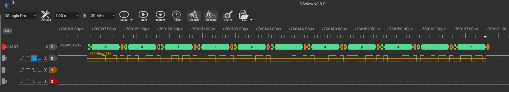
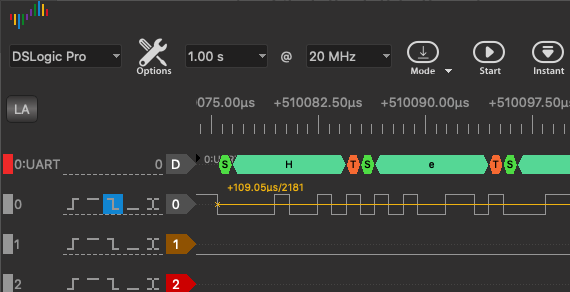
Running the code above for speed of 1mbps I can send for the computer a command using DynamixelWizard, for instance a PING command that looks like this:
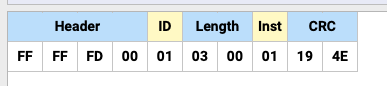
Screenshot 2022-04-01 at 18.36.30

The probe shows:

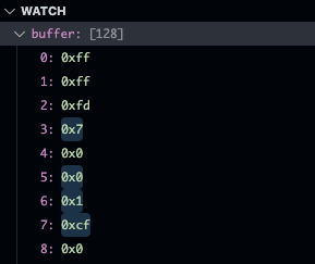
There is no degradation of signal between the two probes and they match the sent message. The program on the controllers stops at the breakpoint and the watch for buffer shows:
Screenshot 2022-04-01 at 18.40.17

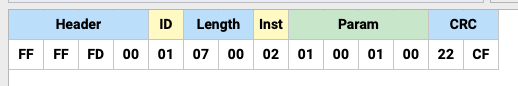
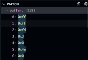
So, at this speed all seems fine, the message was received accurately. To test with a longer message we can try a READ message (from ID 1, starting address 1, length 1):
Screenshot 2022-04-01 at 18.36.40

This one is also received correctly by the controller and the buffer shows:
Screenshot 2022-04-01 at 18.38.47

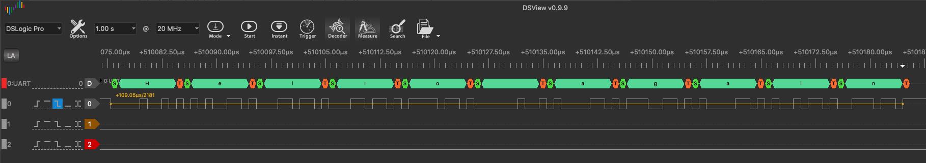
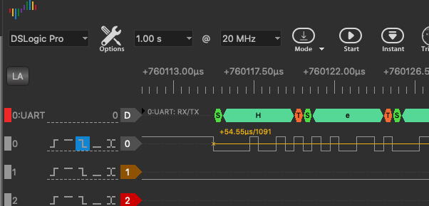
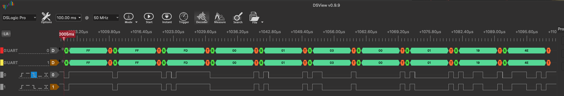
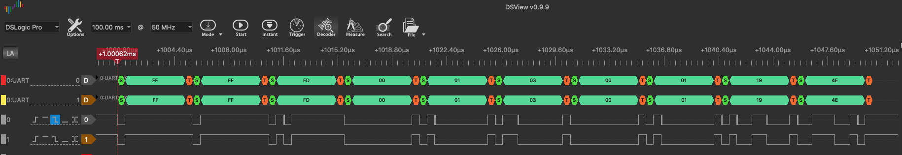
Switching to 2mbps, first sending the same PING message the probe shows:

There is no degradation of the signal, so the message seems to arrive at the RX3 pin correctly. The program though drops bytes from the message:
watchping2mbps

You see that the first 3 bytes were received correctly, then 2 bytes were dropped completely, two bytes again were correctly read, the next two again dropped, and the last one was correctly received.

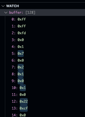
Checking with the longer READ message the script received the following:
watch_read_2mbps
Compared with the original message, again the first 3 bytes were correctly received (0xFF, 0xFF, 0xFD), followed by 2 bytes dropped (0x00, 0x01), two bytes received(0x07, 0x00), two bytes dropped (0x02, 0x01), two bytes read (0x00, 0x01), two dropped (0x00, 0x22) and finally one read (0xCF).

2MBps might be an edge case for the Arduino core implementation then. Have you already checked that the same behavior occurs when you try the Arduino IDE + latest version of GitHub - stm32duino/Arduino_Core_STM32: STM32 core support for Arduino? Then you can directly open an issue at Issues · stm32duino/Arduino_Core_STM32 · GitHub, especially given that the clock settings are already at their highest optimal for your board…