I’ve used PlatformIO to upload programs to a few other types of boards, but I’m stuck on this one. I’ve spent too much time with no results. Please help a beginner get going.
NOTES:
- R10 reads 152
- board reads PC13
- I have options for uploading:
a. mini USB that I used to upload to an ESP32 (aka it has data; not just power)
b. green ST-LINK V2
c. USB TO TTL FT232RL
When I try I get:
...
Configuring upload protocol...
AVAILABLE: blackmagic, cmsis-dap, dfu, jlink, mbed, stlink
CURRENT: upload_protocol = stlink
Uploading .pio/build/bluepill_f103c8/firmware.elf
xPack OpenOCD x86_64 Open On-Chip Debugger 0.11.0+dev (2021-10-17-00:18)
Licensed under GNU GPL v2
For bug reports, read
        http://openocd.org/doc/doxygen/bugs.html
debug_level: 1

hla_swd
none separate

Error: Unable to set adapter speed
Error: init mode failed (unable to connect to the target)
in procedure 'program'
** OpenOCD init failed **
shutdown command invoked

*** [upload] Error 1
I’m just trying to upload a blink sketch like in this tutorial:
Please show how you’ve connected the ST-Link to the Bluepill.
Note that when you connect 3.3V via the St-Link, you don’t need to give it power via the USB cable again.
Additionally connect RST of the ST-Link to the (N)RST pin of the Bluepill.
My bad, I overlooked this error message. This may indicate an old driver on the Windows side or an old firmware on the ST-Link site.
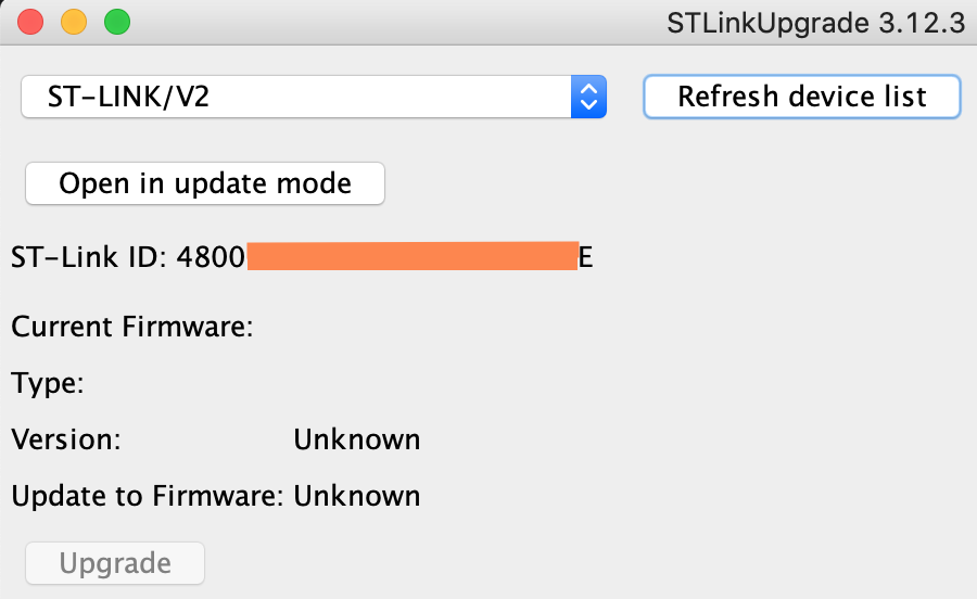
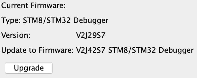
Please download and install STSW-LINK007 - ST-LINK, ST-LINK/V2, ST-LINK/V2-1, STLINK-V3 boards firmware upgrade - STMicroelectronics and upgrade your ST-Link’s firmware version to the latest one.
Thank you maxgerhardt. That did it.
I downloaded and installed the app you suggested.
Clicked
Open in update mode
Clicked
Upgrade
It succeeded.
Then I went back to VS Code and life is great!
The led is blinking according to the delays I have defined, however, I am not seeing any Serial.print output in the Serial Monitor.
I plan to use these boards for fairly simple use cases, but even for simple cases, println is essential 
By default, Serial is the hardware UART (serial) coming out of PA9/PA10.
So, the default expects you to have a USB-to-UART adapter with at least common GND connected and the adapter’s RX connected to the Bluepills PA9 pin (labeled just “A9” on the board).
Of course, you are also able to take advantage of the USB peripheral in the bluepills’s chip. It can open its own USB-CDC interface on the USB port and shows up as a regular serial port on the computer.
To do that, you must
- Configure the compilation flags to enable the USB serial per Difficulty with getting USB serial [USB CDC] working - #6 by maxgerhardt
- Use
SerialUSB instead of Serial in your code just to be sure, per exact code above
-
Remove the 3.3V connection between the ST-Link and the Bluepill
- Plug in the micro-usb cable into the Bluepill and your computer (it will now get its power via the USB cable with no risk of double-powering)
These configuration flags are also documented in
https://docs.platformio.org/en/latest/platforms/ststm32.html#stm32duino-configuration-system
Just a disclaimer: This post may be outdated by now and all you might need to do is add
build_flags =
    -D PIO_FRAMEWORK_ARDUINO_ENABLE_CDC
to the platformio.ini, while still using the regular Serial object. I think PlatformIO’s serial monitor asserts DTR by default now so you don’t need the rest.
But the notes for avoiding double powering should be resepected.
1 Like
Confirmed! Thank you very much for your time.
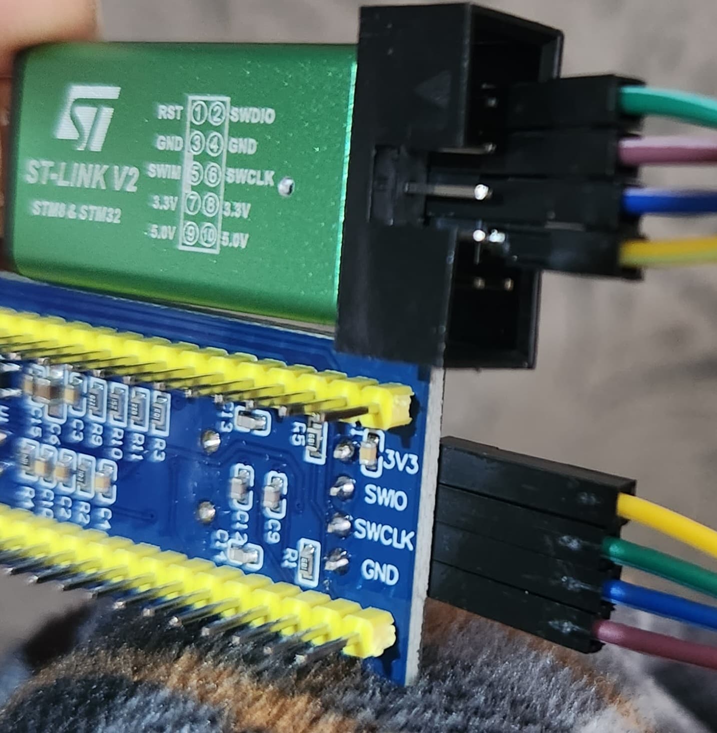
MicroUSB is connected from computer to board.
ST-LINK V2 is connected from computer to board using 3 wires:
- SWDIO → SWIO
- GND → GND
- SWCLK → SWCLK
platformio.ini:
[env:bluepill_f103c8]
build_flags =
  ; enable USB serial
  -D PIO_FRAMEWORK_ARDUINO_ENABLE_CDC
platform = ststm32
board = bluepill_f103c8
framework = arduino
main.cpp:
#include <Arduino.h>
#define LED_PIN PC13
void setup() {
  Serial.begin();
  delay(10000); // wait for Serial to connect
  Serial.println("START");
  pinMode(LED_PIN, OUTPUT);
}
void loop() {
  digitalWrite(LED_PIN, LOW);
  Serial.print("ON");
  delay(2000);
  digitalWrite(LED_PIN, HIGH);
  Serial.println("   OFF");
  delay(500);
}
Great that it’s working!
And just to note, the standard “wait until serial is connected” idiom of
while(!Serial) {}
also works in the STM32 core, blocking execution until “Serial” (through a boolean operator overload) evaluates to true, which it will when the serial port to it is opened.