Congratulations!!
You got transported to “my hero of the quarter” ![]()
In my stripped-down blinky-button sample, PF4 and PF5 do work now!!! I’m pretty sure my register variant will also work now!
![]()
![]()
Congratulations!!
You got transported to “my hero of the quarter” ![]()
In my stripped-down blinky-button sample, PF4 and PF5 do work now!!! I’m pretty sure my register variant will also work now!
![]()
![]()
My dear Max! ![]()
Think I found one more GD32F330x8 issue. Not a big issue, but thought you should know about.
The PCB for which I develop the (alternative) firmware has some hall sensors connected to. Between the Hall-Sensor and the GPIO there’s a N-Channel MOSFET which already has a pull-up R.
Thus I configured the relevant GPIO’s only as pinMode(i.pin, INPUT); cause I thought: “why wasting current, when there’s already an external pull-up”.
All fine with the STM32F030x8… but during my final tests, I recognized that the hall-sensors do not work on the GD32 one ![]() . Has taken me some time and measurement. At first I though I killed the MOSFETs somehow… but then I recognized that I used ‘INPUT’ the first time @ GD32 and tested INPUT-PULLUP, which immediately worked as expected!!
. Has taken me some time and measurement. At first I though I killed the MOSFETs somehow… but then I recognized that I used ‘INPUT’ the first time @ GD32 and tested INPUT-PULLUP, which immediately worked as expected!!
Mean: A simple ‘INPUT’ switches 0V to the input configured GPIO ![]() . I’m fine with using INPUT-PULLUP, but this behavior is somehow risky
. I’m fine with using INPUT-PULLUP, but this behavior is somehow risky ![]()
You mean pinMode(x, INPUT); has a bug and acts like pinMode(x, INPUT_PULLDOWN);? That would be a problem indeed. INPUT should be floating input.
Hi Max!
I worry more worse. Either:
pinMode(x, INPUT); has a bug and acts like pinMode(x, INPUT_PULLDOWN with less than 1k pull down);
pinMode(x, INPUT); has a bug and acts like pinMode(x, OUTPUT);
This is how the hall-sensors get connected (JP4):
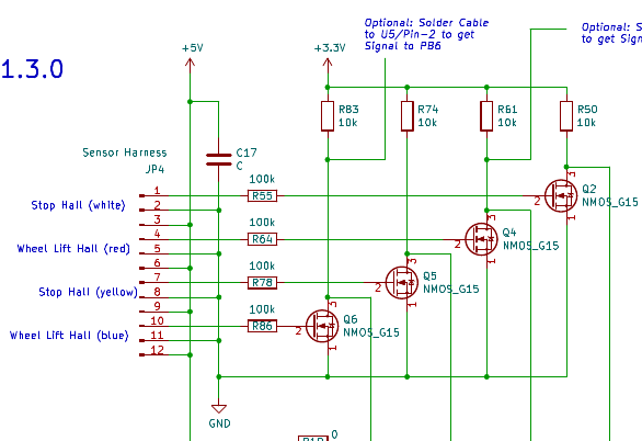
MCU’s GPIO’s are connected to each NMOS Drain (Pin 3). If I do pinMode(x, INPUT);, I measure 0.5-0.7V dependent on hall sate ![]()
In between I double checked if I didn’t made some other stupid failure, but couldn’t find any. As soon as I switch (the GD32 one) to pinMode(x, INPUT_PULLUP) I measure (and get) what’s expected.
STM32 variant work flawless with pinMode(x, INPUT);.
Can that be measured on a pin which is not connected to anything?
Also isn’t it customary to add pull-up or pull-down resistors on a MOSFET’s gate pin to ensure they’re by-default off and there’s not problem with static charge buildup? https://www.youtube.com/watch?v=Wd6NzCY3NgI
Yes, think I’ve a free non-connected one. Will report…
Yes ![]() , think I would do
, think I would do ![]() , but it’s some kind of ready Chinese? PCB. Haven’t found any pull-x while reverse schematic. But might be that I overlooked them during reverse measurement
, but it’s some kind of ready Chinese? PCB. Haven’t found any pull-x while reverse schematic. But might be that I overlooked them during reverse measurement ![]()
Within this Readme there’re some images of the PCB.
Will do the measurement on the free pin…
Did some measuring on unused/free GPIO pin:
pinMode(x, INPUT_PULLUP) = 3.3V => as expectedpinMode(x, INPUT) = 0V => as expectedpinMode(x, INPUT) = 330uA measured via: +3V3 → mA Gauge → 10k R → GPIO Pin. Don’t know how small a pull-down normally is, but expected it would be typically about 40k (like pull-up) => Not good!pinMode(x, INPUT_PULLUP) = 0uA measured via: +3V3 → mA Gauge → 10k R → GPIO Pin => expectedHi Max.
Have to return the lent GD32F330 board soon. Well it’s not a problem for me to use INPUT_PULLUP, but if I’m right with my assumption and measurement, getting an OUTPUT of 0V for a configured INPUT might be somehow risky for other setups.
Tried to dig into it by myself, but turned out that I’m by far not clever enough to understand what get shifted there to where ![]()
I’m not sure what I can do from my side, this may just be different electrical properties of the GD32 chip.
Best you can check if the GPIO registers are correctly set, in sync with the pinMode() call. So for INPUT, the gpio mode has to be set to input, and the gpio pullup register has to be set to no pull, etc. You can check that in the peripherals view during debugging.
If the peripheral bits are set exactly as one would expect, but the chip still exhibits strange behavior – best to ask Gigadevice support.
You already did a lot, and did it again. Missed the option to validate the peripheral registers during debug ![]() . Will do so
. Will do so ![]()
![]()
Hi Max!
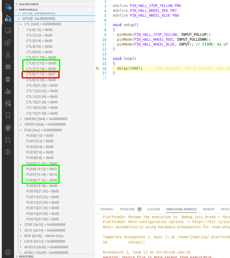
Could do some testing today, and to be sure that’s not some wired failure in my code, I build a tiny test case (also to validate if my register reading is right):
#include <Arduino.h>

#define PIN_HALL_STOP_YELLOW PB6
#define PIN_HALL_WHEEL_RED PB7
#define PIN_HALL_WHEEL_BLUE PB8

void setup()
{
  pinMode(PIN_HALL_STOP_YELLOW, INPUT_PULLUP);
  pinMode(PIN_HALL_WHEEL_RED, INPUT_PULLDOWN);
  pinMode(PIN_HALL_WHEEL_BLUE, INPUT); // FIXME: As of writing 05/13/2023 GD32 has a bug with 'INPUT', which would switch the GPIO to 0V!
}

void loop()
{
  delay(1000);
}
Looks like my feeling that I get a 0V output signal when doing an pinMode(pin, INPUT); (on GD32F330x8) is right, as the peripheral is switched to output mode:
This is btw. also on GPIOA, so not specific to a specific GPIO port.
The frick, I’ll try and reproduce this with your code.
Slightly concerning that “GPIOB → CTL[0x0] = 0x00000000” is shown when there are bits set apparently – slightly out of sync?
![]() , quite thanks
, quite thanks ![]()
Yes ![]() , had it already a couple of times, but thought till now that I probably do something wrong
, had it already a couple of times, but thought till now that I probably do something wrong ![]() , even if there’s not much one can do wrong
, even if there’s not much one can do wrong ![]() ?
?
Holy damn, that’s really a bug. Sad that it was only noticed now.
The internals of the core I inherited are very confusing and needs some major refactor. For different chip series “input” maps to PIN_MODE_INPUT (numerical value 0) or PIN_MODE_IN_FLOATING (numerical value 1). The core indiscriminently used PIN_MODE_IN_FLOATING for all chip series.
OUTPUT, INPUT_ANALOG and OUTPUT_OPEN_DRAIN were similiarly broken, not using the right enum.
This is now fixed in
I’ve tested all pinMode() “mode” type values and the registers are now written to correctly.
Please update + retest.
Hi Max!
Well, that’s unfortunately my determination ![]() . If there’s a trap somewhere, it’s pretty certain that I will step into it
. If there’s a trap somewhere, it’s pretty certain that I will step into it ![]()
![]()
Excellent ![]()
Now it works as expected ![]()
![]()
I’m done now with my project, and need to say: Sincere thanks!! Without your help, we had no GD32 support!!!
Thus: ![]() I’ll not jangle your nerves anymore
I’ll not jangle your nerves anymore ![]()