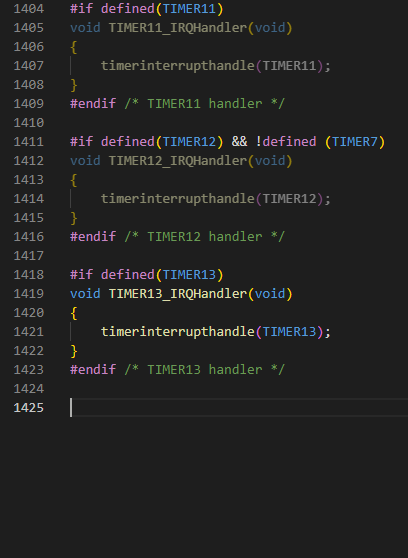
My code is very similar to yours, but I used TIMER14-16 (simply because my previous STM32Cube code also used the “generic” TIM14-TIM16 and TIM14-16 also worked on STM32F030).
But exactly those do not work on GD32F330x8. But TIMER0, 1, 2, 13 do work
I can simply switch over to the working ones, but like to know if it’s an issue or if I read/interpreted the datasheet wrong
In both ways, I fully hit the trap with three legs
For devices within F303xx (not your chip) they can indeed have different timers available and it dependes on the flash size (categories: HighDensity, XtraDensity or ConnectivityLine) there, that hung me up once.Meaning that e.g. for my F303CC, while there is a TIMER13 macro defined, it doesn’t actually have the hardware (and the NVIC interrupt also isn’t defined)
But for your GD32F330 the header files say the TIMER13 interrupt and everything is there. They make no discrimination based on flash size here. No, I think the problem lies on our code because the array used to hold the hardware timer objects is too small (from: HardwareTimer.cpp)
As project proceed, I use more and more of the GPIOs and worry that I found some more wrong ones within GD32F330x8
Unfortunately I can’t evaluate all in one as they’re already routed on my PCB
This time I started with the buttons and had problems with them.
My sources use register mode, but I was able to validate the malfunction also with a simple:
pinMode(<dpin>, INPUT_PULLUP);
if (digitalRead(<dpin>))...
PA11-12 fail.
PB2, 10-15 are okay
PC6-8 are okay
PF4-5 fail
I know, looks wired as it’s not a full bank/register but, but my PCB is also fully mixed with LEDs, Buttons and Mosfets across the ports. So it’s probably a wrong Input/Output/… mode init?
It’s also the first time that I’ve used GPIOF at all. So could be also two issues.
For sure, it could also be that my PCB has a failure, but it looks pretty good.
Would be nice if you could take once more a look into the GD32F330x8 code
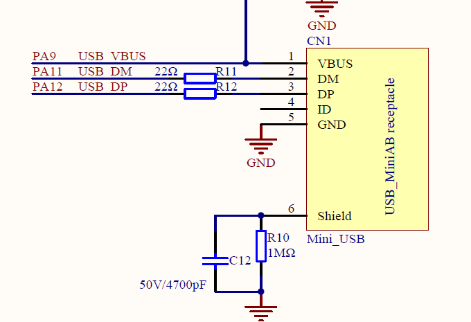
These are USB D+ and D- pins on my board (GD32F350G-START)
So I won’t be able to have direct pin access to those… But my guess is that there either has to be some remapping bit to be set so that they change their I/O function from USB to GPIO or the USB peripheral has to be activated or whatever. At a first search though, the reference manual doesn’t mention anything about it.
Doesn’t seem to be any special pin, not sure why that’s not working. But this pin doesn’t even exist on the package used on my board, so I can’t test. Can only look into the code.
Oh nooo . I’m really sorry. On my PCB those two have also a double use. I forgot to move two 0 Ohm (bridge) SMT R’s!!
How could I forget that I did that also on my STM PCB.
Max, I’m really sorry for this idiotic failure!
But regarding the GPIOF Pins we can assume than, that’s the whole Port as the two buttons on Pin4-5 are the first peripherals I’ve in work now on GPIOF. All other stuff was on the other GPIO ports till now.
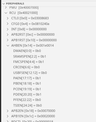
I’ve checked the code again and it seems fine to me. PF4 and PF5 pin macros exist, the code activates GPIOF’s peripheral clock and should write to its registers. Are these still not working? If yes, please Debug->Start Debugging in VSCode and in the “Peripherals” section (lower left), expand the GPIOF peripheral and RCU peripheral with respect to the AHBEN register and screenshot it here.
Moved the R’s and for sure PA11-12 do work! Shame on me
Yes, GPIOF is still not working.
To be sure that I do not bug it somehow, I validated my test-snipped on the STM32 board and compared the PCBs once more. They’re fully identical. Same number, same, building stamp, same parts on it. The only difference is the MCU type.
Here are the screenshots. Hope I made them right:
Quite thanks for your support!! But do not hurry, today is Sunday.
I stopped the debugger after the mains’s setup(), before loop(). As my real code setup all pins for LEDs as well as buttons, pinMode() should have been executed. Not that pinMode() of the test snipped.
However, as I already did a false report, I’ll better make a debug break after the test-snipped’s pinMode()…
UPDATE: Yes, the same. PFEN remain zero, as well as all GPIOF register.
The function is not correctly recognizing that PORTF is the input argument here. A screwup happened where the indices that represent the ports get messed up (Port E not being defined here specifically). A restructuring of the enum or filler data must be inserted here.