Hi all, I’m looking for some support on getting a G431RBT6 (non-nucleo) working on PIO. I’ve got blinky working on Arduino ide (generic board type) but can’t get the same code to work in PIO. I’ve had a go at adding a new board etc to not use the nucleo variant, and tried every build flag I can think of, but it’s hard to tell what is causing the main issue. PIO always builds and uploads okay, but goes into the error handler straight away… Any advice or maybe a git repo I can start with would be much appreciated ![]() .
.
Can you post your base project? (board JSON files, platformio.ini, source code)
If you’re uploading with a debugger, and you look into the call stack once it has gone into the error handler (or Hardfault_Handler()?), what does the call stack look like?
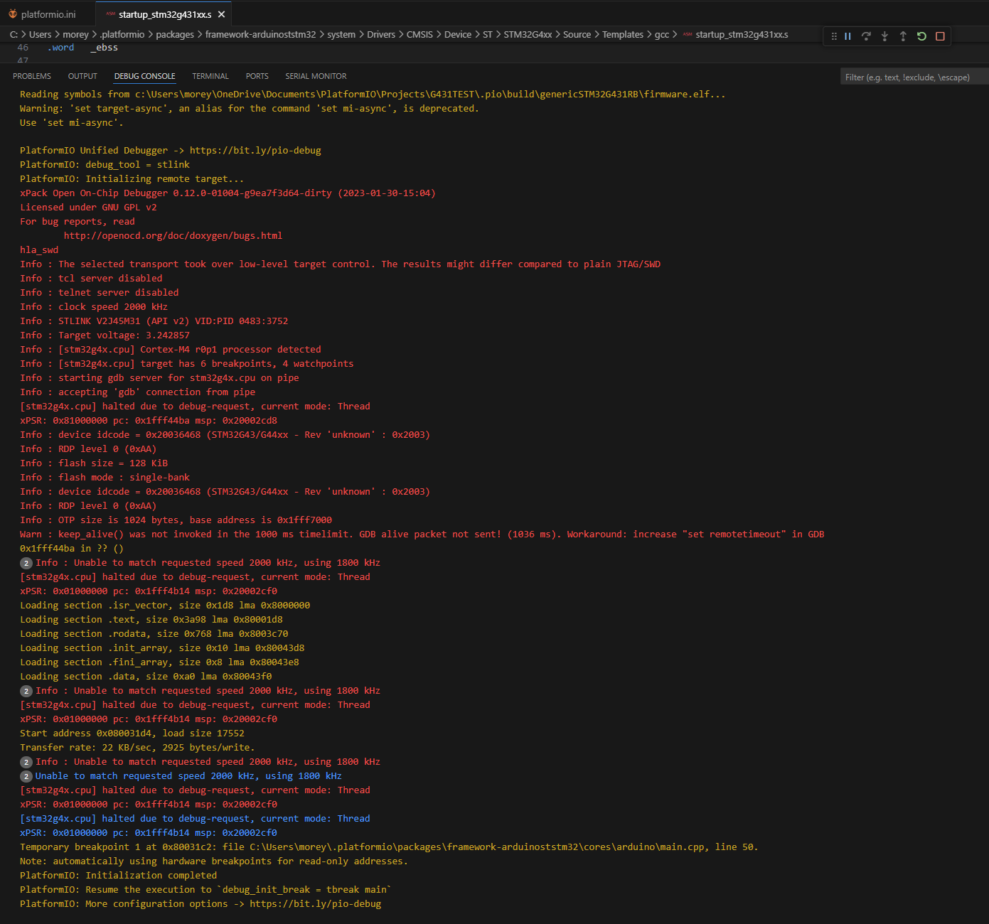
This is my simple test repo. I am using debugger (SWD) something pops into the callstack very briefly but then disappears, so for the most part call stack is empty. So I’m not sure if it’s error or hardfault TBH. I’ve also attached debug terminal output.
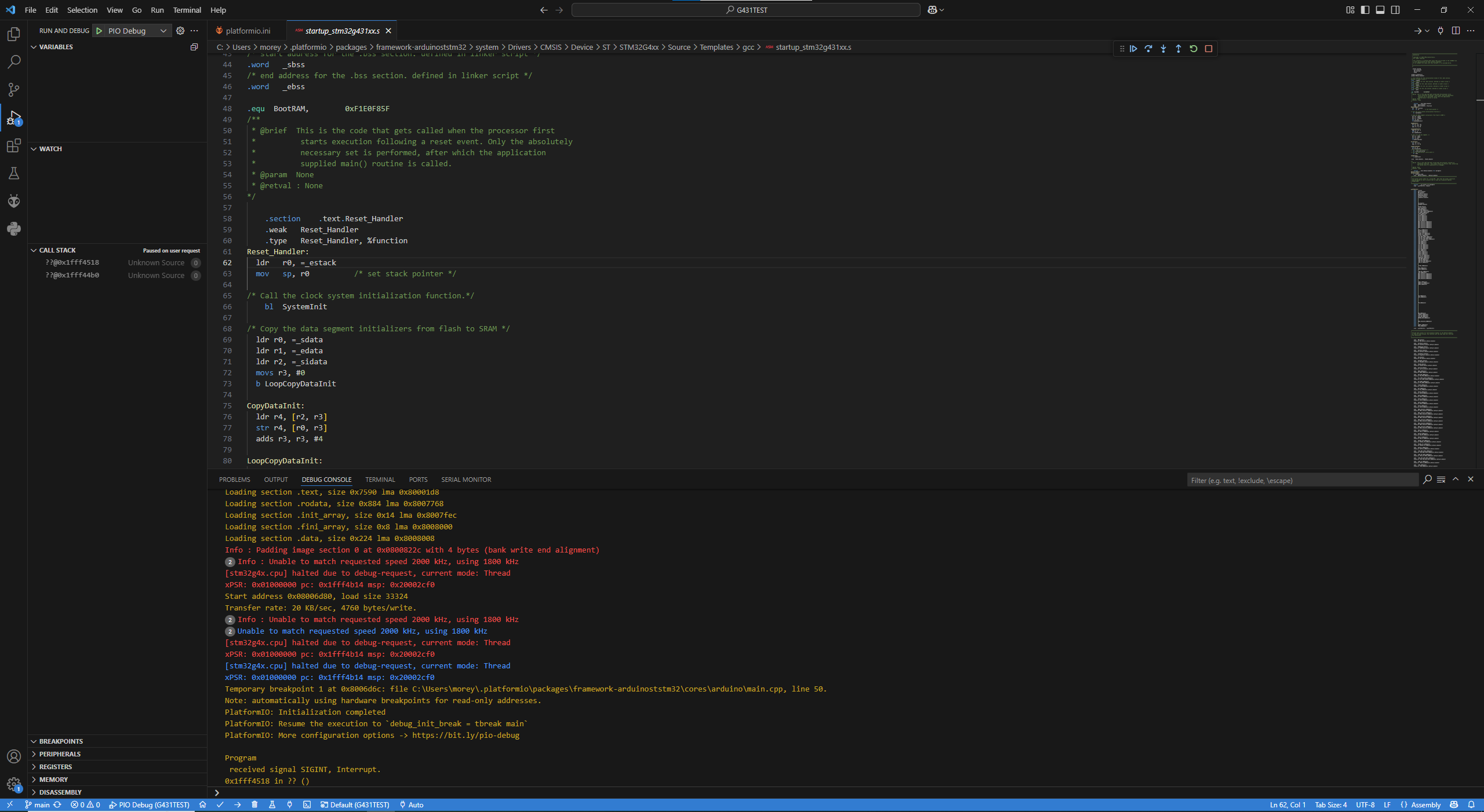
When you click the “Pause” button in this exact situation, what do you see? (full screenshot).
You initialize HSE, but where do you set the expected frequency of the HSE?
With the standard 8 MHz for the HSE_VALUE define, you would be getting some weird 113.333 MHz with those PLL settings.
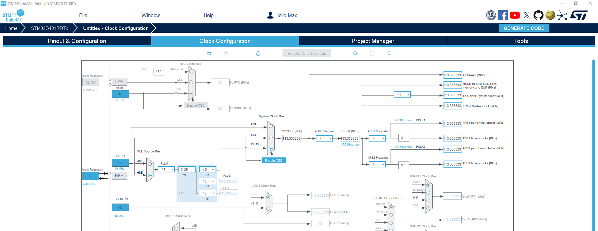
Ah yep sorry I added def HSE build flag just after I pushed that one to git. 12MHz clock should be 170MHz CPU.
-DHSE_VALUE=12000000
Also git updated: GitHub - cmore839/G431TEST
Look at those program counter (pc) values.
They’re in 0x1fff4818. That’s not flash memory where your firmware was burned into. It’s the “System memory” in accordance to the reference manual’s memory map:
page 83.
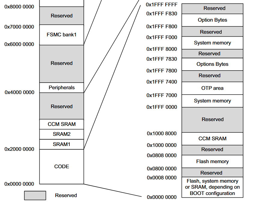
0x1FFFF 0000 up to 0x1FFF 7000 is “System memory”, and 0x1fff4818 is right in there.
“System memory” means bootloader. It should only go there if you have the bootloader pins BOOT0 connected to +3.3V instead of GND. How is that pin connected on your board?
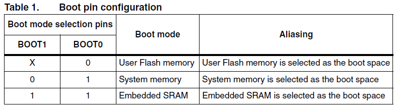
Try connecting that pin to GND, or changing the option bytes as said per First line of reset handler throws exception on STM32G4 - #2 by gfriend
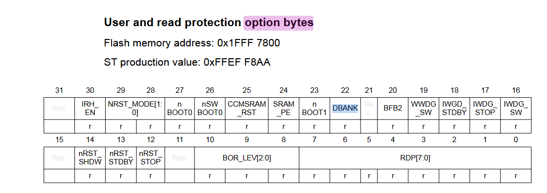
Another possible problem is that the OpenOCD version that PlatformIO uses has a bug with STM32G4, that requires you to use the STM32CubeProgrammer to set the option byte in a way that disabled the “DBANK” (dual bank):
Or, try with the opposite value that you have. (After taking care of the first issue).
See also https://github.com/platformio/platform-ststm32/issues/848 and Compliation failed for STM32G0B1RCT6 MCU with STM32cube framework - #8 by maxgerhardt
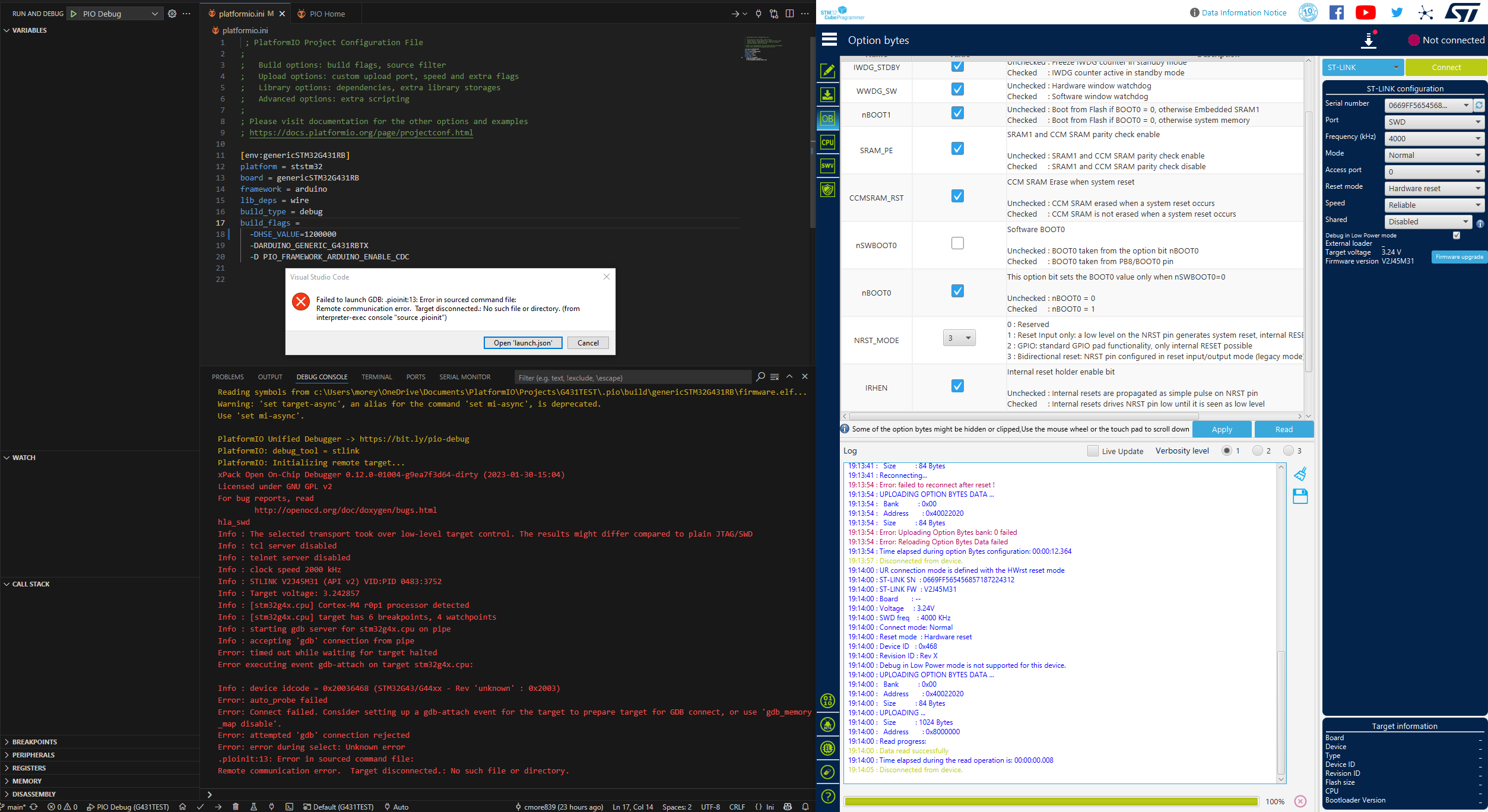
This is my current option bytes. I had found that gfriend post and configured nSWBOOT0 and consequently nBOOT0 to what you see. Seems no change in debugger output… PB8 is connected to Pin#1 of a CAN transceiver (SN65HVD230DR), when not in use I’m not sure if it is high or low… But with nSWBOOT I think that does not matter now.
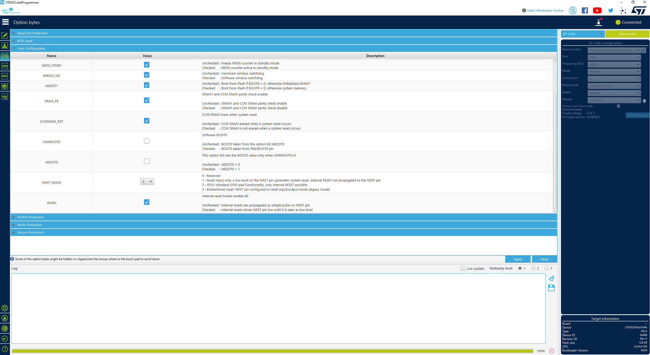
I’ve looked for DBANK, but can’t find it in STM32CubeProgrammer, that screen shot above is pretty much it in OB tab.
Mhm there may be some inversion happening still, because we want BOOT0 = 0, so “nBOOT0” as in “NOT BOOT0” should be “1”. Can you try flipping “nBOOT0” to the opposite value? Don’t forget to disconnect STM32CubeProgrammer again and upload the firmware again in PlatformIO.
Also, weird, the DBANK option bit should be right below nBOOT1, which is present in the screenshot.
Maybe it’s not present for G431 if it’s always single-bank.
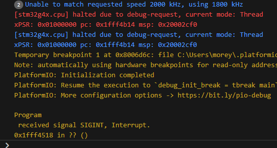
With the nBOOT0 byte not ticked, debug output is same as previous. When I tick the box and save, then disconnect and re-run PIO I get debug error. As seen here:
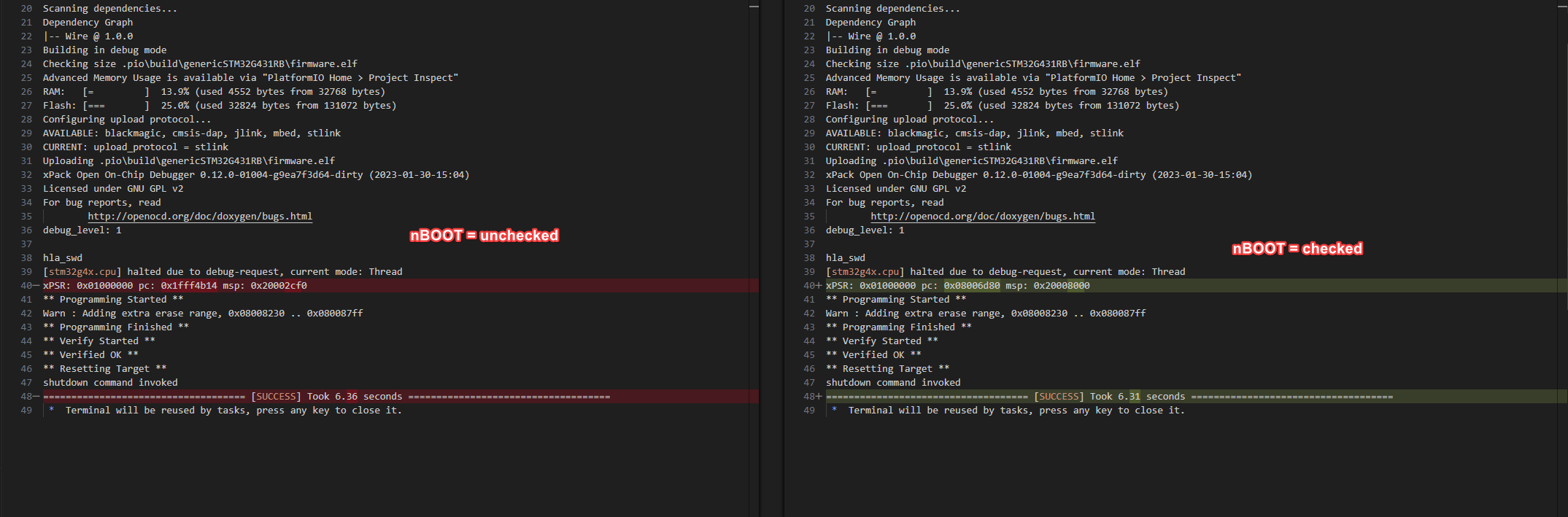
But the weird thing is, even though debug is not working with nBOOT0 checked I can still upload normally, and I noticed the pc: and msp: where different, take a look, it seems like it is going into the right flash area? Unfortunately still no blinking after successful upload
Okay, blinky is working! It was two fold causing the issue.
First was the nSWBOOT0, this needed to be unchecked since PB8 was undefined it was writing into the wrong memory as you mentioned… Seeing this above in previous post gave me some confidence I was on the right track!. Then I pulled out a dev board G431CB and just uploaded the same blinky (mind you with only 4 pins from the debugger, being lazy, 3V3, GND, DIO, CLK) and this worked straight away! What!. So copying the debugger pinout over to my G431RB and low and behold we start to blink… So in the end it was the NRST pin from my debugger causing the last hurdle… But it begs the question, why does OpenOCD do something with the NRST pin, but Arduino IDE does not!? I tried StmCubeIDE too, and NRST pin was fine as well.
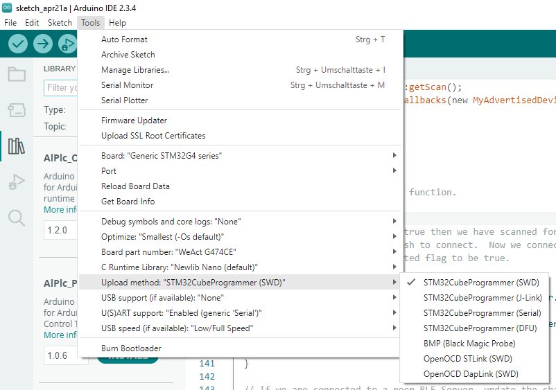
The STM32Duino core in the Arduino IDE uses a different upload method than PlatformIO, no? What do you have selected in the tools → Upload method menu? Also OpenOCD STLink SWD?
Their STM32CubeProgrammer invocation might do some tricks like uploading the firmware and forcing the program counter (PC) to go directly at the start of flash (aka 0x8000000), or invoking a software reset via SWD instead of trying to reset via NRST, thereby still being able to run succesfully with a wrongly setup BOOT0 pin configuration / option bytes and NRST missing or not working.
But, the Arduino IDE uploaded firmware should have failed then if, after uploading, you remove power or press the reset button again. Because then it’s the same scenario as after the OpenOCD upload. Especially if the BOOT0 pins are wrongly setup, after a re-power-up, it should go into bootloader mode and not blink at all. (Or well, most of the time, since the BOOT0 pin is floating and can thus read as a random state, it might not boot up and blink some times.)