Hello Y’all, I am here to present you all with a very weird situation that I am in. I made this custom STM32F411CEU6 board ( GitHub - TheLimboMan/Chongs-Cool-STM32-Board: Chong's Cool STM32 Board ) and I wanted to interface it and program it. I can easily porgram it through SWD just fine, but problem comes when I want to program it either through UART or USB C.
The UART Situation
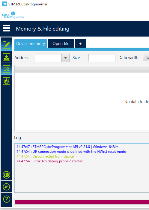
I am interfacing the UART port through PA9 and PA10, which is typically (at least what i see) used on those WeAct BlackPill boards (whose board also hold a STM32F411CEU6), I can get the uart to output into my serial monitor just fine, hello world, sensor output, all just fine, so i assume it shouldn’t be a UART communication problem. but the problem comes when i want to interface it during DFU mode. it just doesn’t work! I used the stm32cubeprogrammer to connect to it, and it just gives out an error telling me to try and reconnect. I hooked up to my serial monitor to see if it gives out “entered bootloader mode” or anything like that, but it just gives me a blank screen!
The USB C Situation
When I connect it through USB C in DFU mode, it gives me a device descriptor request failed! i tried the “pull down PA10” trick that i was told to do, but still nothing. I even tried to pull down PA9 too, along with those SWD pins when i am connecting through USB C but NOTHING, it is still the same. What can i do to fix my situation
Edit: I have tried pulling down the PB2 pin so that boot1 can be pulled down, still nothing
If you press down SW1, do you read 3.3V on BOOT0 pin (or at the upper pin of R8) with respect to GND? have you tried pressing SW1 continously then power-cycling / replugging the USB-C cable, and it’s still not detected?
Here ya go, I think you might be onto something about the DFU not entering properly, because i used a Arduino Mega as a UART programmer by hooking up it’s TX pins to my STM32’s TX pins, then it’s RX pins to my RX pins. UART communication works fine, serial monitor shows, and the RX/TX LEDs on the Arduino Mega lights up normally, just when i enter DFU mode, it all goes dark, No blinking LEDs AT ALL! FYI I also did the whole power cycling thing that you mentioned, but it ain’t working so well either
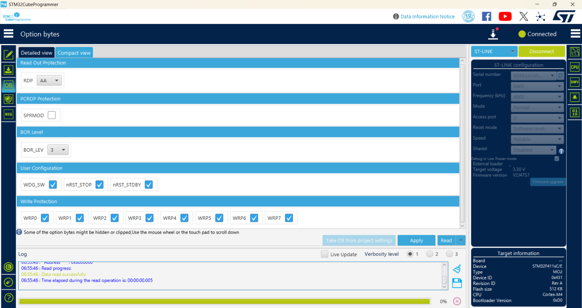
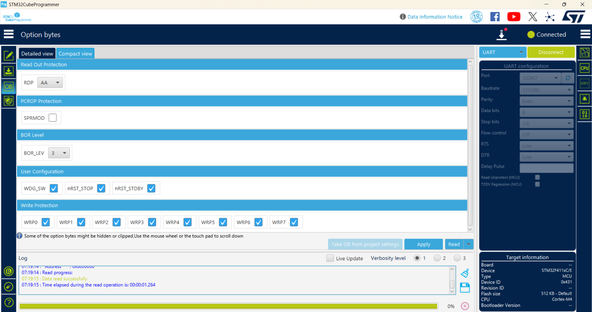
The option bytes look good, specifically the readout protection (RDP) level is “level 1” (0xAA), which means it should be allowed to boot from “system memory bootlaoder”.
If you enter DFU mode via the button and it stops running the regular firmware, that’s actually a good sign. Do you use a dedicated USB-to-UART adapter to interface the STM32 with the PC or do you do that via the Arduino Mega? For the latter, you have to absolutely disable the Mega2560 on the Arduino Mega from driving the lines, by connecting the RESET pin to GND; That lets the USB-to-UART chip on the Arduino Mega board drive the line completely.
Can you upload a regular Arduino-STM32 firmware that tries to establish a USB Serial connection? You have to take special care to inform the build system that your HSE crystal is 24 MHz (and not e.g. 25 MHz like used in the Blackpill F411 design).
What’s your current platformio.ini? Do you already set HSE_VALUE in it? Do you use a custom board JSON definition? Do you already use a custom clock init function that enables HSE+PLL?
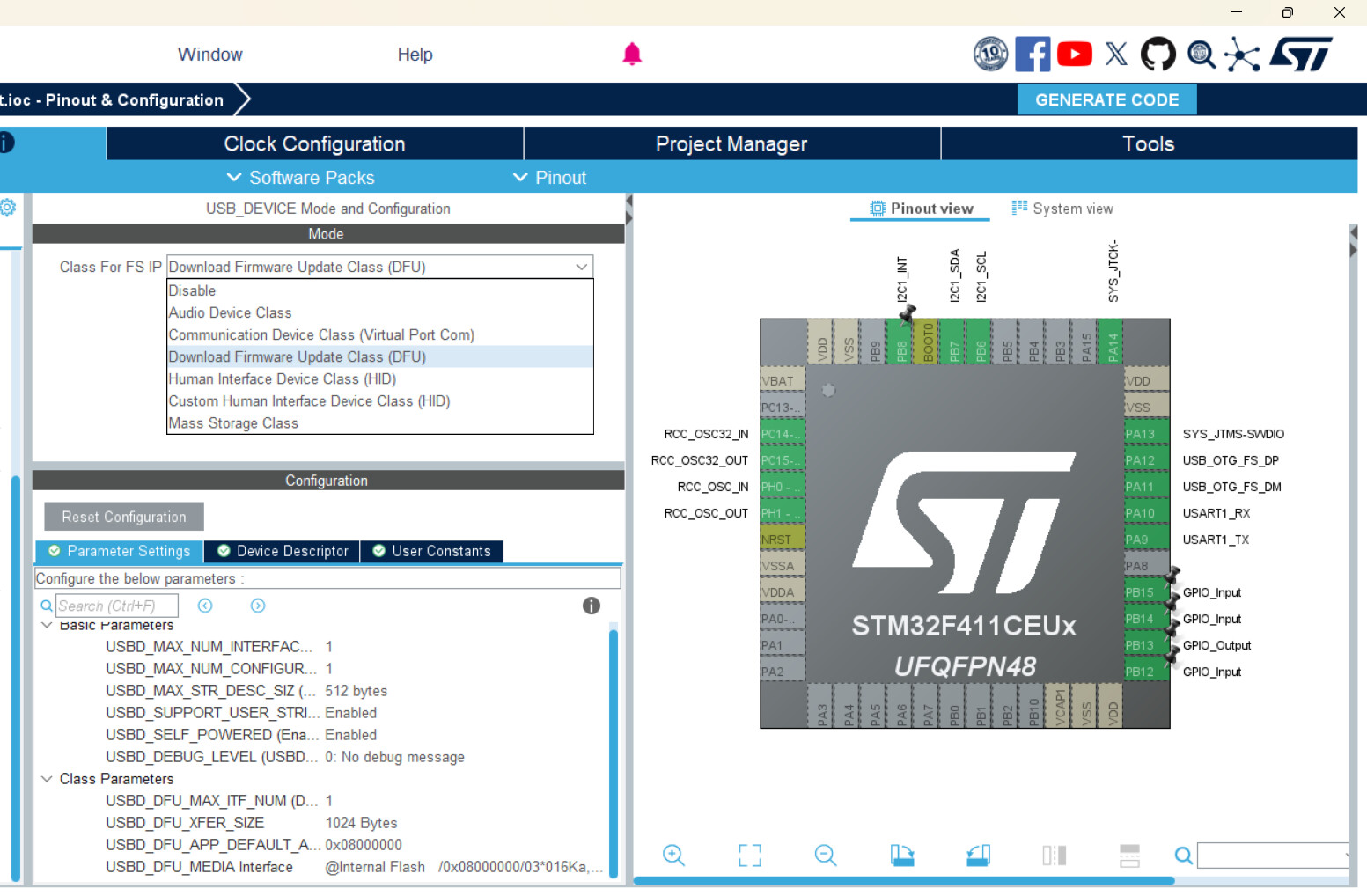
In STM32CubeIDE, I’ve set the USB_DEVICE to both Virtual Port COM and DFU, both allowed me to plug in my STM32 into my computer without the need for switching to DFU Mode, but it still gives me DEVICE DESCRIPTOR FAILED in device manager
I assume this is what you mean by uploading a firmware that can allow me to interact through USB? Because I don’t think i can find an Arduino-STM32 firmware somewhere that is compatible (at least i think they don’t) with my stm32 board since the pinouts are all different so i am doing this instead.
Edit: Clock is already configured according to my clock selection, both input clocks are set to 32.768 and 24 mhz respectively
Sorry, that means if you set it to “Virtual COM Port”, the device was able to show up as a proper COM port on your computer via USB? No “device descriptor failed” message there, but only in bootloader mode?
nope i meant that if i set it to virtual com port it also says device descriptor failed
Edit: and just to be extra clear, i also tried the whole grounding the PA10 pin and also PB2 pin when the device is in virtual com port mode too, still nothing
Nope, i uploaded it, plugged it in without entering DFU and it isn’t showing ANYTHING at all on my device manager, not even a device descriptor error, no COM port too. Thanks for the code btw
I have tried the blinking code (but my led is on PB13 so i call for that instead) it doesn’t seem to work
but i think that’s a software issue because if i use STM32CUBEIDE and use their own special codes and syntaxes and all that stuff i was able to make it blink, read my gyroscope and so on
Crystal wise, i think it should be wired up correctly, I’ve been basing this board on that Phill’s lab tutorial:
I have some suspicions that the crystal is not soldered properly (i hand soldered them myself)
The crystals are quite similar to the LEDs that I’ve soldered, they both only have contact pads exclusively at their bottoms, meaning the solder can’t grip on the sides like those SMD capacitors and resistors
When i initially solder on my LEDs by just placing them onto the pad, heating them up until they move into place by themselves, they don’t seem to work, its right until i press them down while heating them up again that they seem to work
It feels like it’s a similar situation with the crystals, i think all i need to do is to reflow the solder and press down the crystals more so that they can make more contact
Man I really wish it didn’t have to come to this, pulling out my soldering kit again is such a hassle
Oh this is the weirdest part, it doesn’t work too! It really only works when i use STM32CubeIDE, with the whole
while (1)
{
    /* USER CODE END WHILE */
	 HAL_GPIO_TogglePin(GPIOB, GPIO_PIN_13);
	 HAL_Delay(500);
    /* USER CODE BEGIN 3 */
}
thing, along with all the other function declarations and callings and stuff
I have also a suspision that the stock bootloader/firmware (or at least the compiler files) doesn’t really allow me to interface my board with anything from Arduino.h and the arduino framwork for some reason
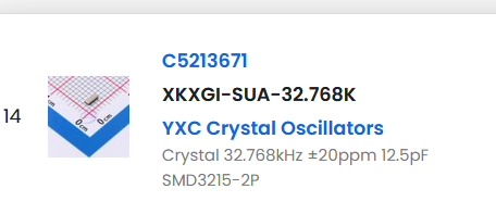
Do you guys think the fact that i connected up the wrong capacitors-crystal combo is causing the USB functionality to not work? I have this 12.5pF crystal, and my board connects this crystal to a 1.5pF capacitor (which i think is quite too low according to CL = (C1 * C2) / (C1 + C2) + Cstray?)
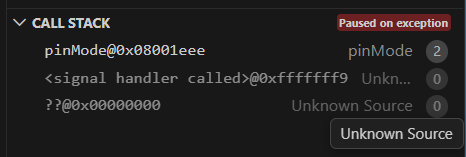
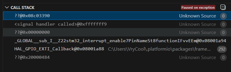
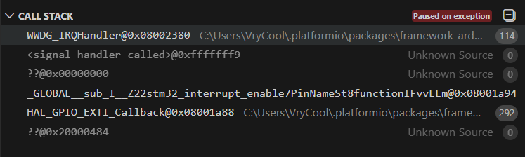
That should not be possible. With the firmware exactly from STM32 DFU not working through UART and USB - #15 by maxgerhardt, and using an ST-Link, can you go to the debug side bar and press “Start Debug”? If it boots up, press the “Pause” after some time. What is the call stack?