I am trying to use Software serial for my Rp2040. But when I complie with the PicoSoftwareSerial the code copmiles and everything but I get this error when I connect a TTL USB to Rx and Tx.
17:02:04.438 -> ++ MbedOS Error Info ++

17:02:04.438 -> Error Status: 0x80010133 Code: 307 Module: 1

17:02:04.438 -> Error Message: Mutex: 0x20002980, Not allowed in ISR context

17:02:04.438 -> Location: 0x1000533B

17:02:04.438 -> Error Value: 0x20002980

17:02:04.438 -> Current Thread: main Id: 0x20002794 Entry: 0x1000525D StackSize: 0x8000 StackMem: 0x200029C8 SP: 0x2000A784

17:02:04.471 -> For more info, visit: https://mbed.com/s/error?error=0x80010133&osver=61700&core=0x410CC601&comp=2&ver=90200&tgt=NANO_RP2040_C...

17:02:04.471 ->

17:02:04.471 -> -- MbedOS Error Info --
You’re already taking this up with the library author, which is good, but then also link to it.
https://github.com/beegee-tokyo/PicoSoftwareSerial/issues/1
Does this mean it works in the Arduino IDE but not in PlatformIO?
I have used the <SoftwareSerial.h> library which works on Arduino but I can not find a similar package that would work for PlatformIO. all the other packages did not compile but this one did and it Is giving me the error
Oh, I see well. Well, whatever it is, it ends up trying to acquire a mutex within an interrupt routine, which doesn’t work. But:
- If you want to keep using the ArduinoCore-mbed (and not the alternative Arduino-Pico) core, keep in mind that you have
Serial1, Serial2 (and Serial3 which is just Serial2 without flow control pins) available, as the RP2040 has two hardware UART peripherals, in addition to the USB serial. You can see the default pins for them here and can just use them like the regular Serial object. So if you only need two hardware serials, then you already have them.
- You can use the Arduino-Pico core also in PlatformIO if you closely follow the manual.
- this core again exposes both UART perpiherals as
Serial1 and Serial2 (see here) and here
- this core has a built-in
SerialPIO library, using the PIO state machines to implement the UART. It is documented here. It even has this exposed with the standard conforming SoftwareSerial.h header for compatibility, so you can just #include <SoftwareSerial.h> and it’ll come from the core and work automatically.
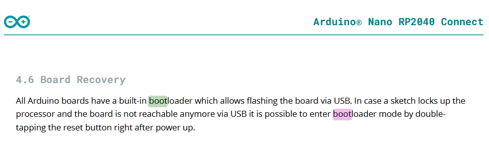
Thank you!! Can you also suggest how to reflash my Rp2040? I grounded REC and put it in bootloader mode and uploaded a BlinkingLight firmware and still it goes back to the Error state
Yup!! I figured it out!! Thanks
Weird board schematics, the pin headers have “RESETN” on both sides, but the JP2 one with the QSPI_CSn is what usually functions as the “BOOT” pin. The right “RESETN” is the RUN pin of the RP2040.
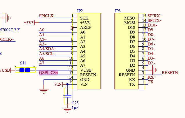
If you connect that QSPI_CSn signal to GND, then it should boot in USB UF2 bootloader mode and create a USB drive.
The regular Raspberry Pi Pico schematics have he BOOTSEL button implemented as a button that, when pressed, connects the QSPI_SS (= CS) signal to GND.