SKR 1.4 Turbo Motherboard Without SD-CARD Reader! Bricked?

you need a fine soldering tip and just come and place the tinned wire

solder r

If i understand you correctly?

no,
below

is too small to solder!!!
no other way??

i failed to solder to the SD-M vias! i have even less chance to successfully solder to the resistor.

here, but you have to add a 10k resistor
image

merci [tokaphi]

same issue!
too small i think without additional equipment eg hotair gun

but to clarify… the wiring is this what is required to correct?

OR alternatively

I think i may just possibly be able to solder to Y
thank you that is more viable option
(i hope not to desolder or damage the component also (lol!)

i might have to invest into hot-air soldering station (useful for future)
except it will be more expensive than replacing the skr 1.4!!!

i will attempt the fix - it is certainly worth a try!

merci for the continued input
i appreciate your efforts to educate an idiot!

Hm both sides of the resistor shouldn’t go through the to the 0.8-MOSI header. I’m deducing from the I and J connections that the left side of the resistor must go the header (and must also be connected to the SD card SPI signals). So this is what we get from the known tested connections

So the solder points are clear after all, to the left of D7 and to the left of R55.

In this diagram, CD should be solderer to the left of Diode D7, becuase the bootloader will use pin P0.27 which is connected to the original SD card holder; P0.26 on the SPI header is a different pin. Of course, there is a chance that this pin might also be ignored by the bootloader – only way to be sure it to test it with and without that connection. All other connections are correct.

Hm I personally would not use hot air. You would also need kapton tape to isolate the plastic headers (e.g. SPI) so that they don’t melt. Really, a soldering iron with a small tip is good enough. You will need some practice of course and the right technique. For example, you should add solder to the left side of the resistor (or diode) and also to one end of the wire first (“pre-tinning”). Then just bring the pre-tinned components together, touch both of them with the fine soldering iron to melt them, then back off.

There are even “SMD practice boards” available on e.g. aliexpress or ebay, which have all sorts of SMD components (and sizes) to help you practice. And a soldering iron with a few tips also doesn’t cost much (maybe 20-30€)? Youtube also has a ton of tutorials (https://www.youtube.com/watch?v=QKbJxytERvg, https://www.youtube.com/watch?v=QzoPxvIM2qE, https://www.youtube.com/watch?v=b9FC9fAlfQE)

But you’re right, with the materials and tools and practice needed, it might cost more than a new SKR 1.4 mainboard, so don’t spend too much on it :slight_smile:

I have ordered a new soldering iron with some fine tips
I am just waiting on the delivery
i shall try to repair it and will let you know how i get on

thanks again for your kind instructions

Good Evening Community.platformio.org

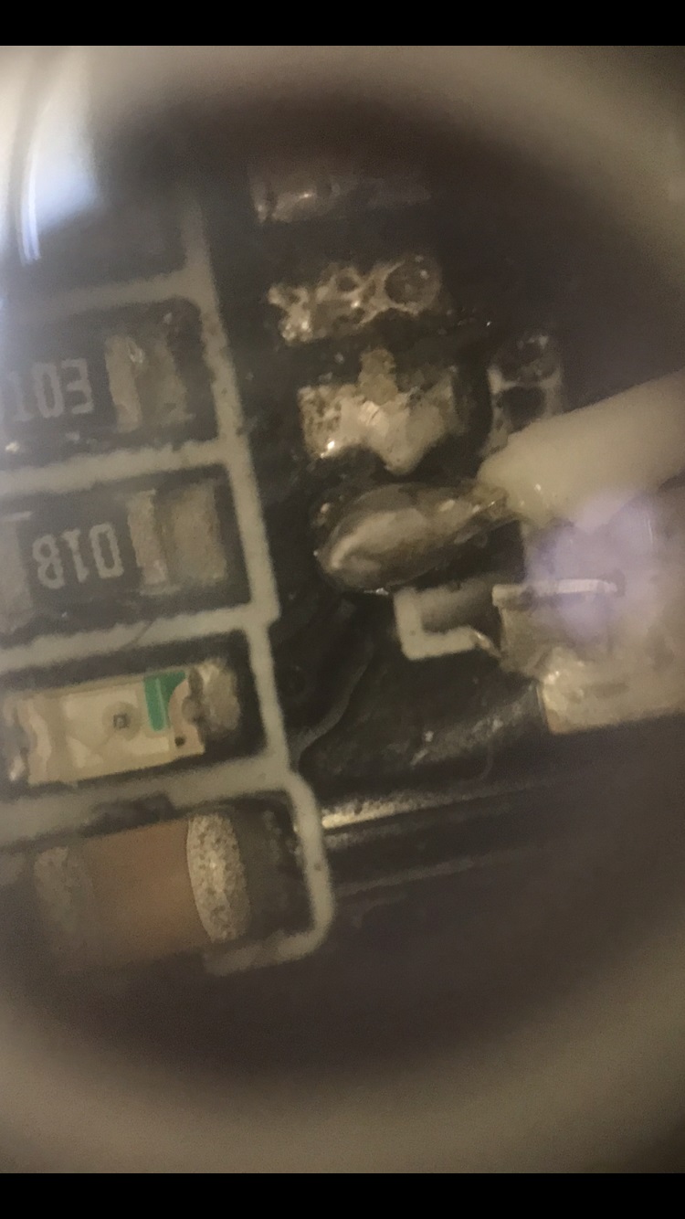
So i have managed to attach(solder) the wires connecting the Adafruit 5v ready Micro-SD Breakout Board to in place of the damaged/removed SKR 1.4 Turbo Micro-SD Connecter.
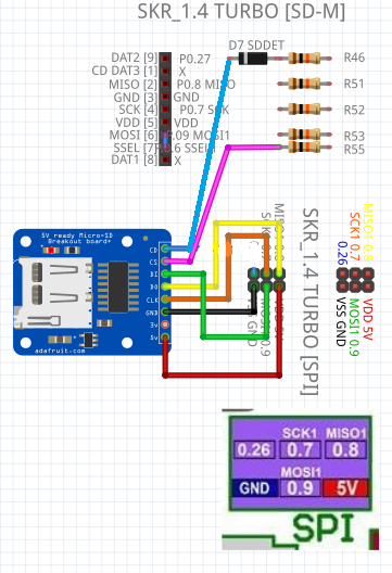
using the schematic i uploaded and following the corrections from the kind assistance provided.here…

Unfortunately It is not working !

Diagnostic: skr turbo connected to pc via usb

  1. on board sd-led on the skr turbo is off by default
  2. when i connect the 5 wire SPI connector (excluding SPI 0.26)
    on board sd-led on the skr turbo turns on

3. inserting the sd-card -

  • 3.1 does not open the usb drive on computer)
  • 3.2 on board sd-led on the skr turbo turns off

Can anyone please elude to what may be the issue?


→ SD-BREAKOUT BOARD PIN [CS]

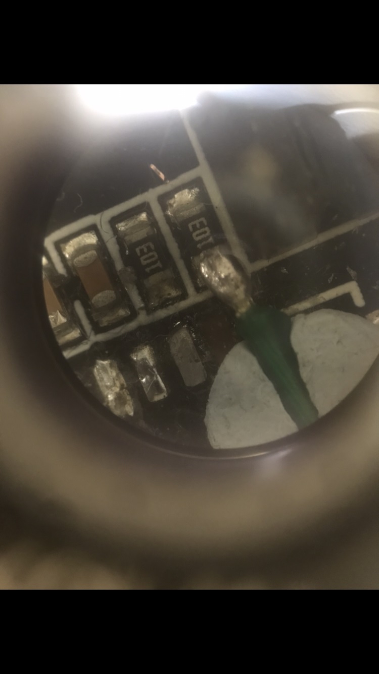
→ SD-BREAKOUT BOARD PIN [CD]

Update :slightly_smiling_face:

So the marlin SDCard01 USB Device Is available in Windows Device Manager.
i have determined that it was not working previously as
I was working inside a virtual machine instance and the usb was connected to the host.

However :
when inserting the card it can not be read
windows explorer/Disk manager : shows disk but no media
i have validated 3 separate micro-sd cards to ensure not sd-problem

can anyone help?

    1. is the wiring correct? have i made a mistake?
    1. is it possible my jumper wires are too long?
      if so… is it possible to use jumper wires at all or on any wires??

Success ! The SD-CARD works!
the sd-card will not work until the skr-1.4 turbo is reset!
It was not an issue with the modification or the length of the wiring (I did check). the sd-card also works if the CD is connected to SPI 0.26)

Thank you for all the support without you i would have never worked it out!

i improved my soldering technique as a bonus
the amusing thing is actually that the skr 1.4 turbo sd module was ‘in the way’ in respect to fitting in an extremely tight space in the 3d printer body (its how i broke it)
*i have managed to get it out of the way *
and this will allow more options in placement.

1 Like

what microscope is that? where can I buy one?

Really interesting topic! I ordered two SD card readers because I thought I could make this work, but both micro SD card breakout boards do not have a CD and CLK pin… I guess that makes them completely useless.

Guess I’ll have to wait for the replacement SMD slot. Managed to order them from China, because literally no Dutch company sells these.

Let’s hope I manage to solder on the new microSD slot haha.

Can you show the pinout of your SD-card breakout board? It might be called differently. Like “DET” for detect instead of card-detect (CD) or SCLK (SPI Clock) instead of CLK.

Thanks for your reply, sadly it only has six pins!
CS
SCK
MOSI
MOSO
VCC
GND

So the pins are literally missing. There are also no additional terminals to solder on for additional functions… What I think it the saddest is that I just bought something that will now spend time in a drawer forever without being used :slight_smile: I really don’t like to waste resources. Maybe I’ll find a use for it some day? Who knows.

I’m guessing the CLK pin goes to a pin on the MOSFET to activate the power on maybe.

It’s this model:

Seems to be a HW-125
Here’s more data about this exact card:

This is the SPI clock. CLK, SCLK, SCK, all these names stand for the same thing here. You see SCK1 even being the signal name for it in e.g.

So the only thing you’re missing is the card-detect pin / SDDET. Otherwise you can try the same thing as above. If it doesn’t work, you can try and connect SDDET to 3.3V or GND on start to fake it being detected. You can even connect it to a switch (SPDT style) to switch SDDET between 0V and 3.3V.

Thus I don’t see a reason why this wouldn’t work with the hardware you don’t have.

So with a reference to the above picture and your SD card module, your pinout from SD module to printer board should be
CS → left side of R55
SCK → SCK1 0.7 (on SPI header, yellow wire)
MOSI → MOSI1 0.9 (on SPI header, green wire)
MISO → MISO1 0.8 (on SPI header, yellow wire)
VCC → VDD 5V (on SPI header, red wire)
GND → VSS GND (on SPI header, black wire)

Left side of D7 LED either unconnected or to GND or to 3V3 or to a switch to switch it between GND and 3V3).

1 Like

Thanks, I didn’t realize SCK was clock, makes sense haha.

So, what would be the problem if I don’t have SDDET? Would I have to perform a special operation when inserting an SD card? I think in that case maybe it’s wise to wait until I receive the actual component before I try this workaround.

That depends on what the bootloader does. We don’t know whether it reads the voltage on that pin at all or if it reacts to it or needs that signal, but it is connected to the microcontroller.

Now either:

  • The SD detection is not used at all and thus would not require you to solder a wire
  • The SD card detection is used and you need to pull the line to the right voltage.
    • If the device is always expected to have a SD card inserted, you can solder a wire between the SDDET signal and GND or 3.3V
    • not 100% sure which voltage it needs to register as ‘inserted’, but based on the schematic above the SDDET LED lights up when the left side of it goes to GND (the right has 3.3V). So if "LED is lighted = card is inserted) then you should try GND first
    • if the device does not always have a card inserted you need to either
      • buy a SD card module which has the CD / card detect pin and use that (e.g., full micro-sd breakout with no conversion logic, CD would be DAT2 per schematics above, refer here)
      • connect a switch SPDT switch to the SDDET signal to switch it between GND and 3.3V. If you then insert a SD card into the reader, you have you also flip the switch in the right position (GND or 3.3V) so that the bootloader recognizes the card (or not recognize it when you don’t have one inserted).
1 Like

Thanks, I’m pretty new to all this. So I’ll first try to connect the microSD slot when it arrives and if that fails I have the backup.

Thanks for sharing your knowledge, it helps a lot to get a bit more insight into how these things work :slight_smile:

ps in my country, the Netherlands it’s quite hard to source these things. I only found 6-pin breakout boards. So I’ll have to go on Aliexpress anyway. Then I’d rather wait for the replacement slot to arrive.