Hello all,
Hope you guys are having a good day. I am currently working on a project where I need to communicate from a cellular module to an Arduino Due and vice versa.
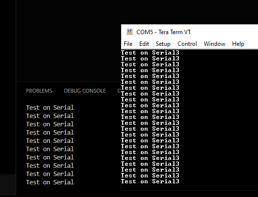
I am sending commands to the arduino through Serial3 the TX3 port, but it is not working. I am very confused because I am also “sniffing” the port to see if the data is being sent out but it is not, I am getting nothing. I have used Serial3 in the past with other projects but it never has given me this issue.
When I use a Normal ‘Serial.print()’ statement, I get a printed message on the serial monitor. I am working this project on a scheduler, so I have two serial monitors open (one for sniffing the TX3 pin, and one for displaying the normal serial monitor). And within my code, I have both ‘Serial3.print()’ and ‘Serial.print()’ right next to each other, but I am only getting data on the normal serial monitor.
My code is very long so I will not show it all, but if anyone would like to see parts of it, I would be more than happy to share.
Are there any things off the top of your head that might help in figuring out what is messing with the communication from Serial3? I am not using any of the RX/TX pins for anything, so maybe something I am doing in the code is not working?
I have Serial3.begin(115200) in my setup. I don’t know what else could be stopping the Serial communication. I’ve also tried printing on both serial lines but only Serial.print(); seems to be working.
Try and reduce the number of active components in your sketch in large blocks, maybe at some point it suddently gets unblocked again and you thus found the problem.
Otherwise I can offer to take a look at your full code if you upload it somewhere.
Of course, a more direct way of debugging this would be to use a hardware debugging probe, like an Atmel-ICE, CMSIS-DAP, etc. and just step into the Serial3.print() call to maybe see where it bails out, whether it writes to the UART registers, what the state of the GPIO configuration registers is etc. I’m assuming you don’t have that.
Haha, assumed right. I want one now that I see what people say about them online, they seem amazing. Do you know which would be best for Due. I am fairly new to this Arduino programming but just as I was starting to get a little bit comfortable I now hear about debugging and debugging hardware haha.
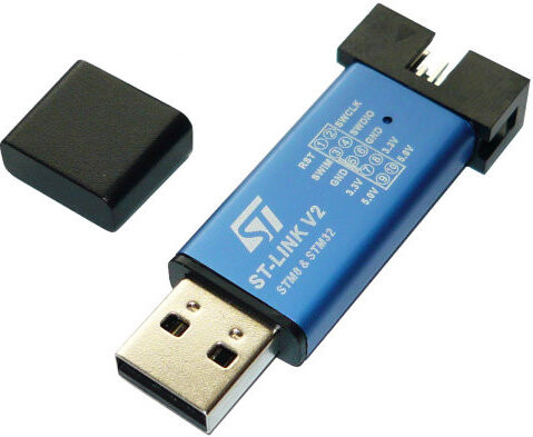
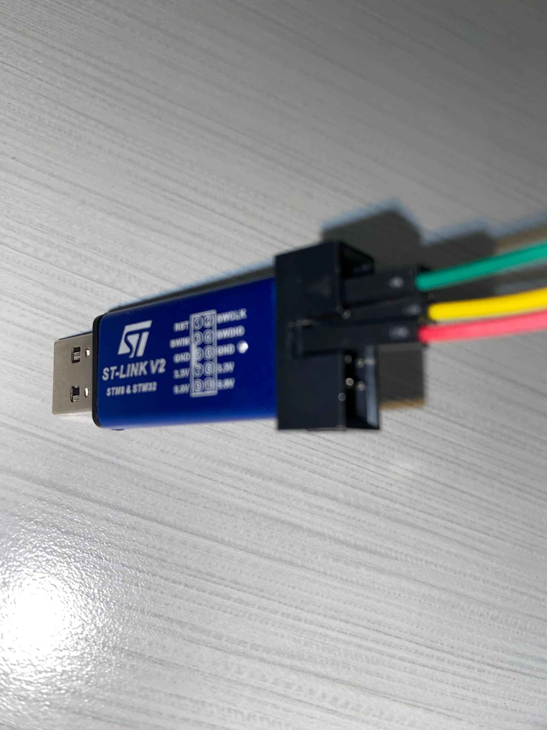
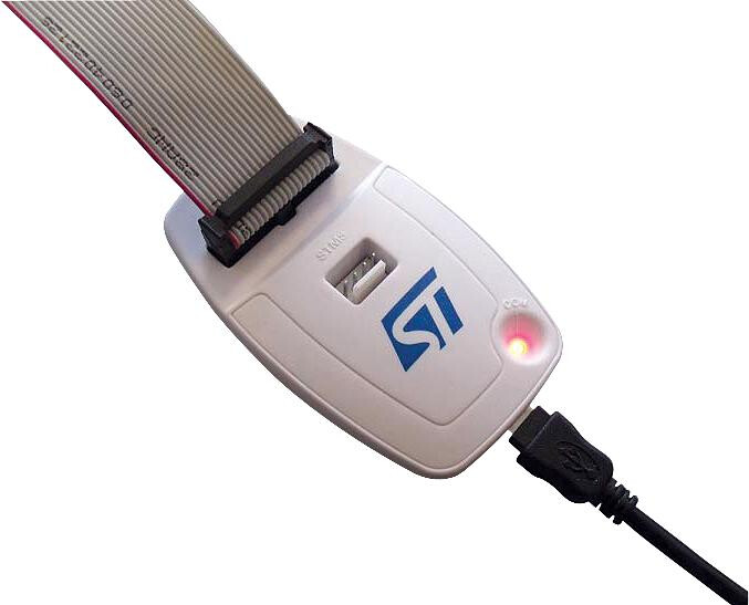
the STLink is the cheapest, with clones costing like 5€. All the other listed ones are prohibitively expensive for hobbyists. The STLink has general SWD connections (SWDIO+SWDCLK), so it’s not limited to STM32 processors, but can do other ARMs too, like the MCU on the Due. I use my ST-Link for debugging various chips a lot and it hasn’t failed me yet.
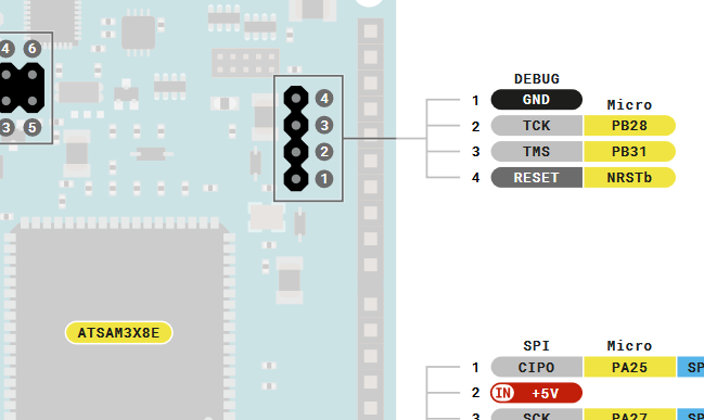
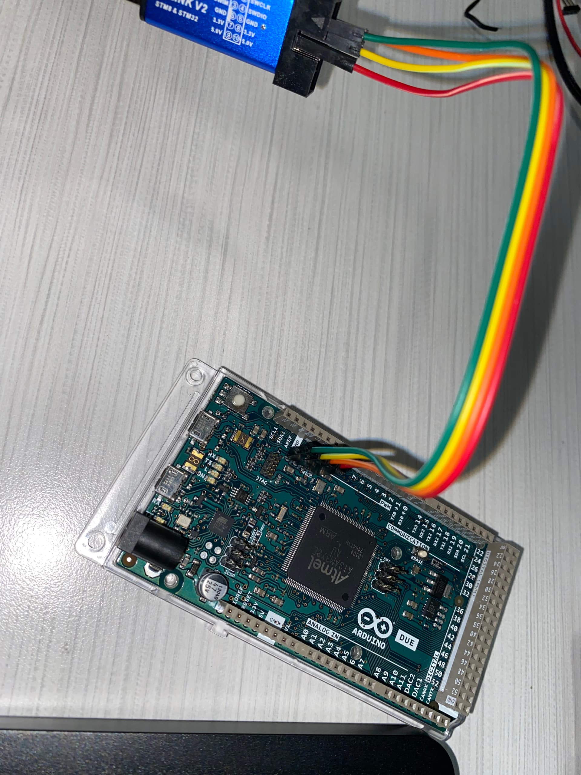
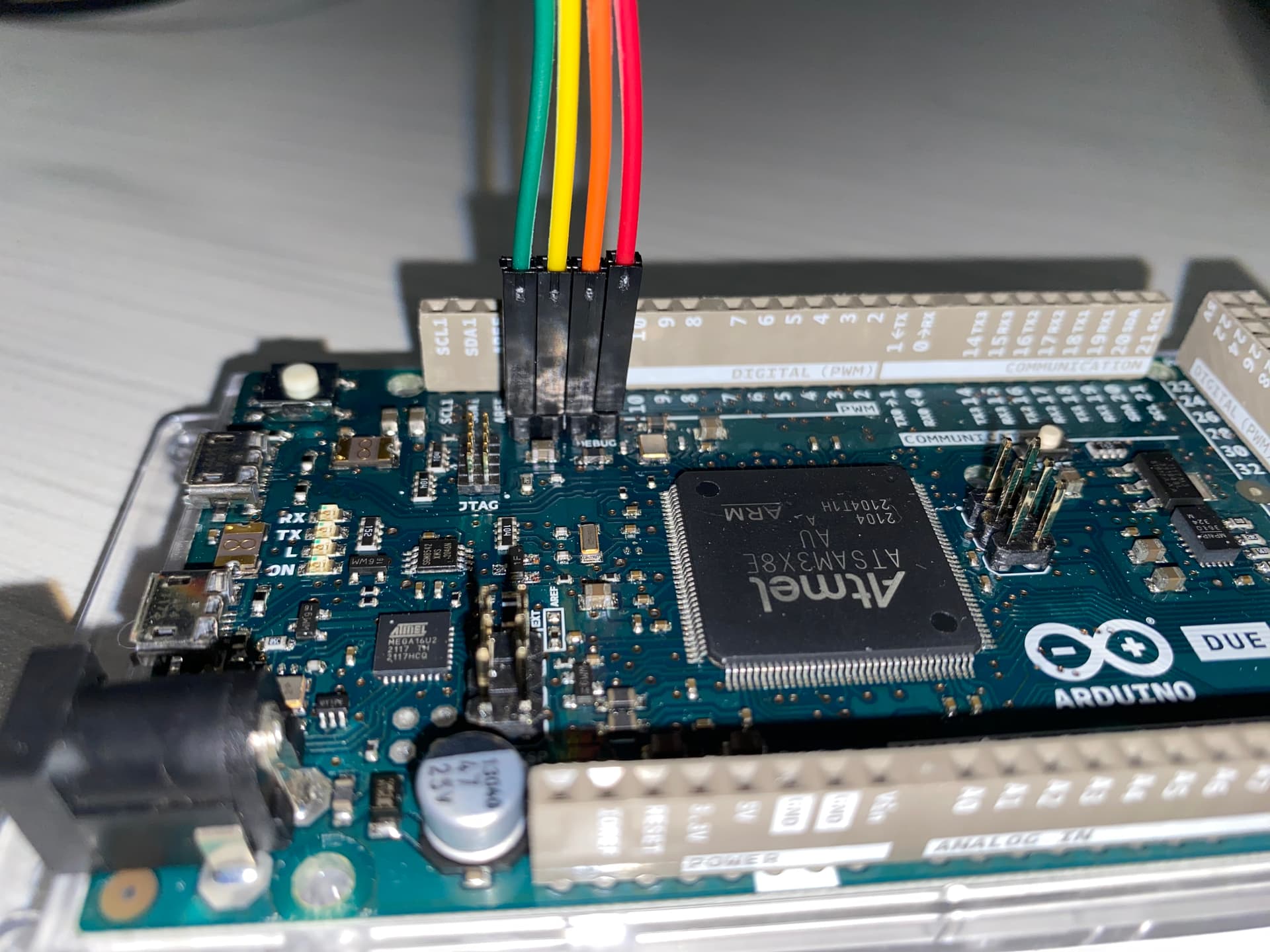
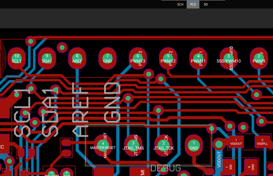
Note, when you have such a debugger, you must make the SWDIO connections between the Due and your debugger per pinout. The “DEBUG” header has all needed signals, and TCK (testclock) is “SWDCLK”, “TMS” is SWDIO and RESET is also nRST. Those will also be labeled on the STLink. Additionally, you need common GND (aka GND from STLink to GND of Due).
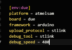
To tell PlatformIO that you are now using an ST-Link, you have to configure your platformio.inias documented with
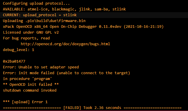
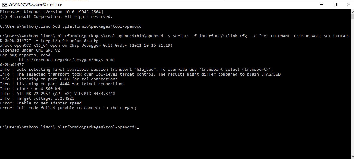
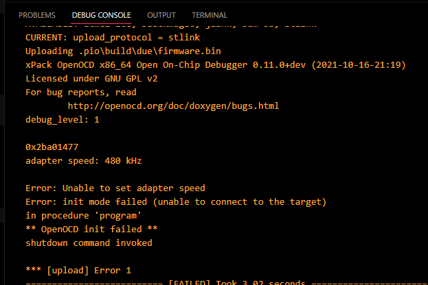
Okay so it must be that simple then. This is the error I am receiving in the debug console, regardless of the success message in the terminal.
Am I missing on adding something to my configurations/launch.json file?
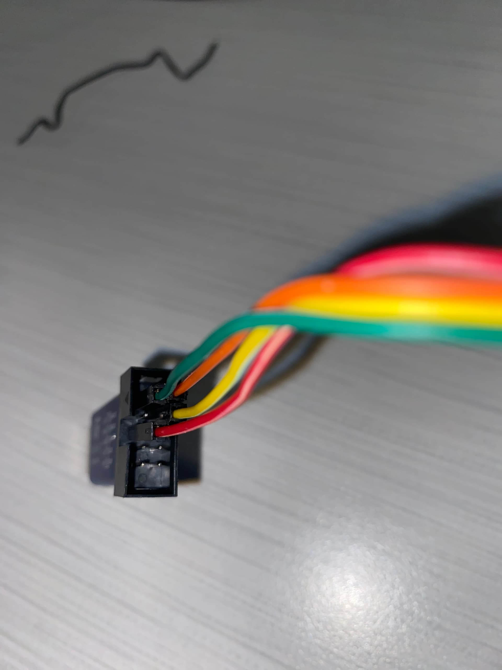
Of course. I can show you setup. I did also connect it to USB. But here are some pictures. Before I show the pictures, I will mention that I tried this same setup with both a USB and AC socket as power and they both resulted in the same error.
Also, does it matter if the power is supplied through Programming port or Native Port? I also used 5v supply and 6v supply when connecting to the AC socket.
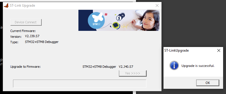
I also think I should mention that I was able to get my hands on one of these from a friend of mine at school
However, when connecting it and running a debug, I still got 2 errors, except the “Unable to set adapter speed” error was switched out with one saying that the target voltage was too low.
This post confirms it should be working on ST-Link v2. There’s also this config file but it’s basically the same as the command above already.
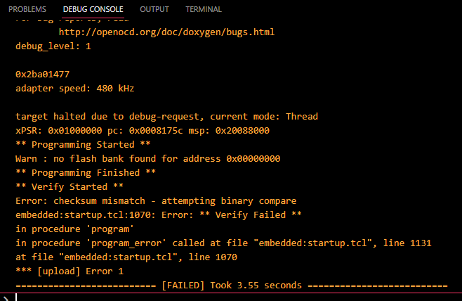
The “unable to set adapter speed” may be a smoking gun here, that shouldn’t fail with the default speed of 500kHz, it should just adjust to use 480kHz instead.
Can you please set
debug_speed = 480
in the platformio.ini and try debugging again? Is the error message now gone in the Debug Console?
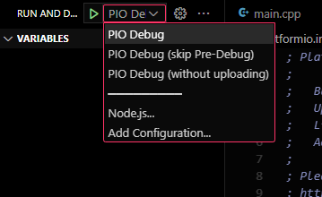
Just to make sure, after clicking on the run and debug tab, I just need to run the debug on the “PIO Debug” configuration, right? Because besides that I am not doing anything else in the debug section besides switching from Debug Console to Terminal, and vice versa.
This was the result of changing the debug_speed and running the PIO Debug
I will follow your instruction on updating immediately after this.