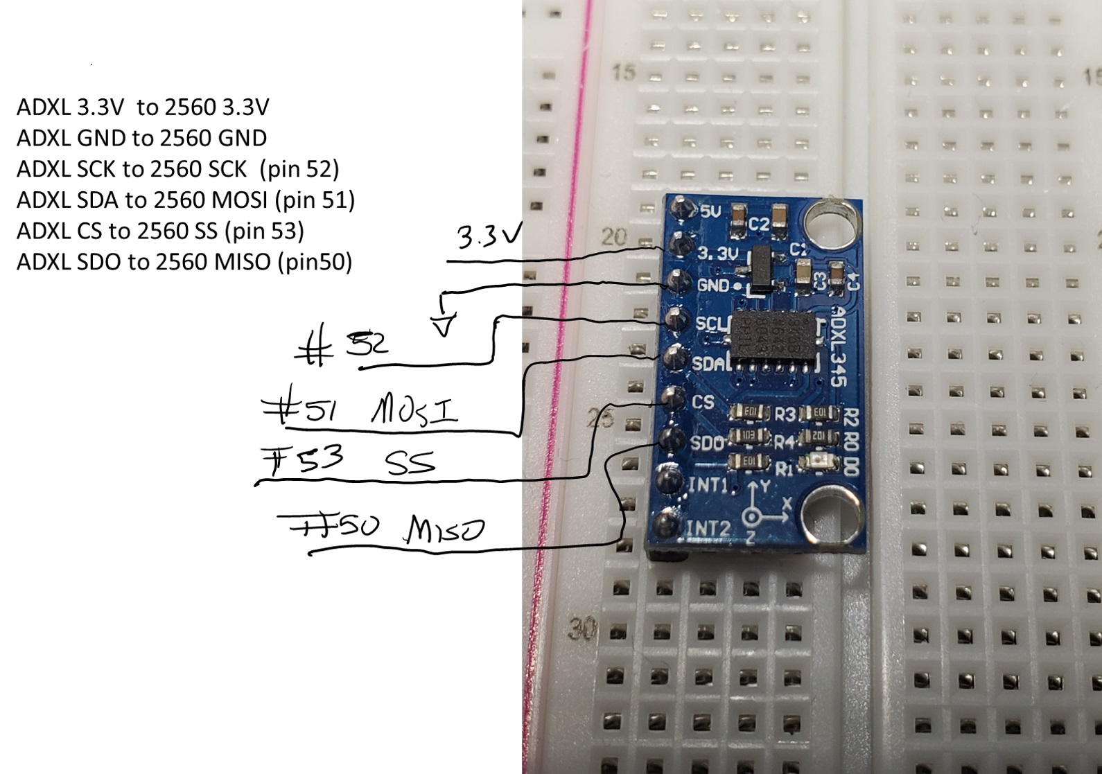
My class is using PlatformIO IDE to develop their own code for SPI read and write. We are doing a lab where we read data from the ADXL345 accelerometer (all 3 axis).
To see the values of the x,y and z axis - we are using the Serial.print(); statement. There seems to be an issue with it working sometimes and not working. I have changed the serial.flush command location but there is still an intermittent issue.
Moderator edit: added code formatting tags and removed blank lines
Here is the platformio file contents:
; PlatformIO Project Configuration File
;
;   Build options: build flags, source filter
;   Upload options: custom upload port, speed and extra flags
;   Library options: dependencies, extra library storages
;   Advanced options: extra scripting
;
; Please visit documentation for the other options and examples
; https://docs.platformio.org/page/projectconf.html

[env:megaatmega2560]
platform = atmelavr
board = megaatmega2560
framework = arduino
Here is the code:
main():
#include <Arduino.h>
#include <avr/io.h>
#include "spi.h"

unsigned char POWER_CTL = 0x2D;   // Power Control Register
unsigned char DATA_FORMAT = 0x31; // Data Format Register

int main(){
  // Set baud rate for serial transmission, flush before printing anything
  Serial.begin(9600);
  //Serial.flush();
  // initialize SPI
  //Serial.println("initSPI()");

  initSPI();
  spi_write(POWER_CTL, 0x08);   // set to measure mode
  spi_write(DATA_FORMAT, 0x00); // configure 4-wire mode by clearing the SPI bit

  while(1){
    // Read current XYZ position from ADXL345
    Serial.println("readAccel()");
    Serial.flush();

    readAccel();
    printCoords();
    // Delay for 1000 ms
  _delay_ms(1000);
  }
  return 0;
}
spi.ccp
#include <Arduino.h>
#include "spi.h"
#include <avr/io.h>

#define wait_for_completion while(!(SPSR & (1<<SPIF)));
unsigned char DATAX0_REG = 0x32;      // X-Axis Data 0 Register
unsigned char DATAX1_REG = 0x33;      // X-Axis Data 1 Register
unsigned char DATAY0_REG = 0x34;      // Y-Axis Data 0 Register
unsigned char DATAY1_REG = 0x35;      // Y-Axis Data 1 Register
unsigned char DATAZ0_REG = 0x36;      // Z-Axis Data 0 Register
unsigned char DATAZ1_REG = 0x37;      // Z-Axis Data 1 Register
unsigned char dataX0, dataX1, dataY0, dataY1, dataZ0, dataZ1;
int dataX, dataY, dataZ;

void initSPI(){
  // set the SS, MOSI, and SCLK pin as output
  DDRB |= (1 << DDB0) | (1 << DDB1) | (1 << DDB2);
  // set the MISO pin as input
  DDRB &= ~(1 << DDB3);
  // set SS high at first
  PORTB |= (1 << PORTB0);
  // enable the interrupt, SPI, master mode, CPOL, CPHA, default clock, and fosc/128
  //ADXL345 CPOL = 1, CPHA = 1
  SPCR |= (1 << SPIE) | (1 << SPE) | (1 << MSTR) | (1 << CPOL)| (1 << CPHA)| (1 << SPR1) | (1 << SPR0);
  // Initialize data read variables
  dataX0 = 0;
  dataX1 = 0;
  dataX = 0;
  dataY0 = 0;
  dataY1 = 0;
  dataY = 0;
  dataZ0 = 0;
  dataZ1 = 0;
  dataZ = 0;
  /*Serial.print("X: ");
  Serial.println(dataX);
  Serial.print("Y: ");
  Serial.println(dataY);
  Serial.print("Z: ");
  Serial.println(dataZ);
  Serial.println();*/
}

/*
write to a register of an SPI device
regAddress = register address of the SPI device
value = value to be written to the specified register of the SPI device
*/
void spi_write(unsigned char regAddress, unsigned char value){
  // set SS low to begin SPI frame
  PORTB &= ~(1 << PORTB0);
  SPDR = regAddress;
  wait_for_completion;
  SPDR = value;
  wait_for_completion;
  // set SS high to end SPI frame
  PORTB |= (1 << PORTB0);
  //_delay_ms(1000);
}

unsigned char spi_read (unsigned char regAddress)
{
  // 0x80 = read mask; 0x00 = dummy value to be sent
  spi_write (0x80 | regAddress, 0x00);
  return SPDR;
}

void readAccel(){
  // Read X0 & X1 Data
  dataX0 = spi_read(DATAX0_REG);
  dataX1 = spi_read(DATAX1_REG);
  // Combine X0 and X1
  dataX = (dataX1 << 8) | dataX0;
  // Read Y0 & Y1 Data
  dataY0 = spi_read(DATAY0_REG);
  dataY1 = spi_read(DATAY1_REG);
  // Combine Y0 and Y1
  dataY = (dataY1 << 8) | dataY0;
  // Read X0 & Z1 Data
  dataZ0 = spi_read(DATAZ0_REG);
  dataZ1 = spi_read(DATAZ1_REG);
  // Combine X0 and X1
  dataZ = (dataZ1 << 8) | dataZ0;
}

void printCoords(){
  //Serial.flush();
  Serial.print("X: ");
  Serial.println(dataX);
  Serial.print("Y: ");
  Serial.println(dataY);
  Serial.print("Z: ");
  Serial.println(dataZ);
  Serial.println();
}