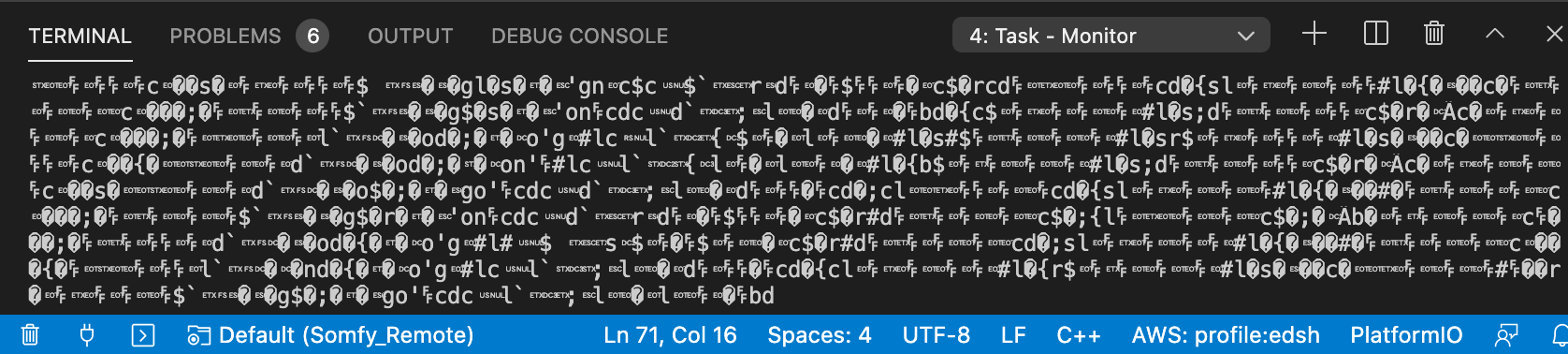
However when I plug in an FS1000 transmitter and restart the device by pressing reset, I get an infinite scrolling of weird characters that seem to repeat:
Eventually (after 20, 30 seconds) my Visual Studio Code crashes, I guess the buffer just went full.
An upload in this case also doesn’t work:
loading .pio/build/d1_mini_pro/firmware.bin
esptool.py v3.0
Serial port /dev/cu.usbserial-1410
Connecting........_____....._____....._____....._____....._____....._____....._____

A fatal error occurred: Failed to connect to ESP8266: Timed out waiting for packet header
it just eventually time-outs.
However if I unplug the 5V of my transmitter, (re)start the D1 mini again (by pressing reset for example), everything works; and I even can re-connect the 5V!
So TL;DR: booting with a load on +5V somehow makes the (serial) interface unavailable?
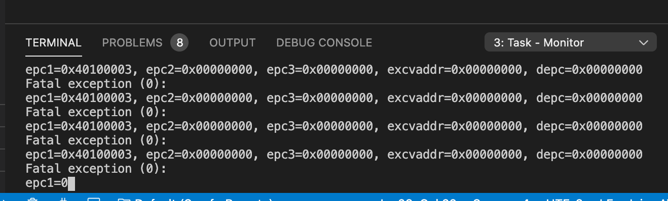
and repeat the same experiment? You should get your normal output at first, and after plugging in your transmitter and restarting the device, maybe now the output won’t be garbled, but the output from the ESP8266’s bootloader code telling something has happened, like an error reading out flash, and it will try to reboot, over and over again, but the transmitter is still affecting the circuit so nothing changes…
They are read on bootup to determine certain settings (which mode to boot into, bootloader or normal application or SD card, which flash voltage to use that was on the ESP32). If these are wrong the ESP will indeed not boot…
Is your transmitter module placed on one of these critical GPIO pins?
absolutely… apparently I misunderstood/confused the many forks of this kind of project and eventually used the wrong pin, i.e. GPIO2!
I now tried D1 (i.e. GPIO 5) which works fine.
Now when I’m looking for it the Internet is full of notices saying some Pins must not be HIGH or LOW on boot etcpp…
Thanks again a lot for your help! I’ve learned a lot already. And I can throw the PCB I’ve ordered in the bin
I’ve read a bit into it and it seems these GPIOs just shouldn’t be used, and I second that. I’ll wait until my (first ever) PCBs arrive, examine them and will take the opportunity to improve them anyways.
Thanks a lot again!