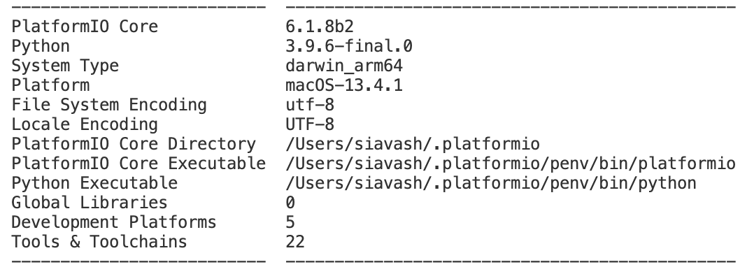
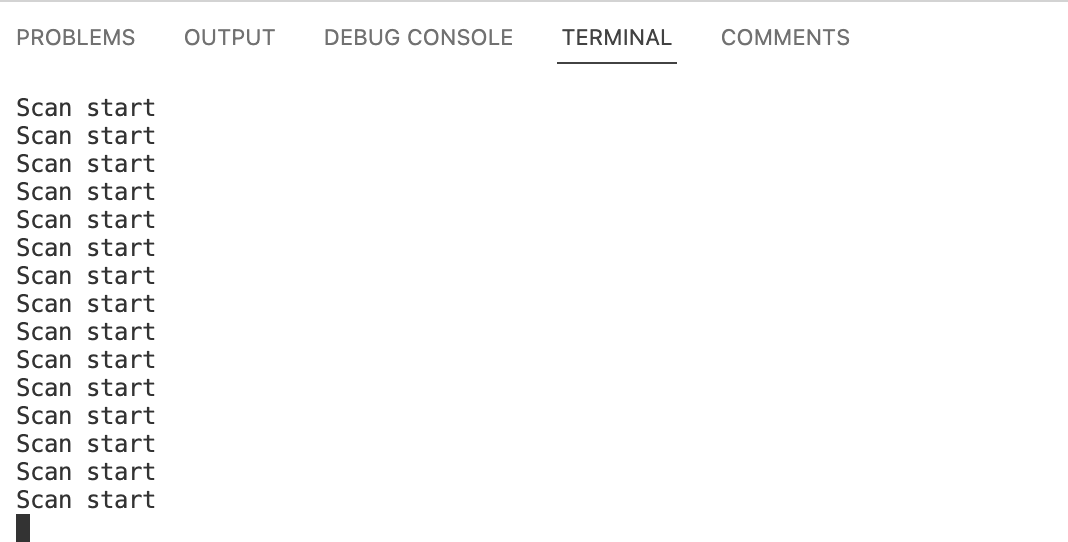
Serial Monitor does not produce expected output. It prints nothing or random characters or legit code messages but at rapid succession. I get no errors during upload. When I close VS Code and start Arduio IDE Monitor (changing nothing else), Arduino Monitor works properly. I have updated my VS Code environment:
ESP32 CAM % pio upgrade
You’re up-to-date!
PlatformIO 6.1.8b3 is currently the newest version available.
Looks like while I was writing my original post a new PlatformIO Core was released! So now I am on 6.1.8.b3. Unfortunately problem still persists.
That did not help. I tried each followed by pio device monitor.
Sometimes I get blank output, sometimes ‘Scan start’ and other times ‘Scan start’ followed by ‘Setup done’.
Managed to get it working 
Reconnecting USB cable to the computer and then pressing reset button on ESP32CAM seems to solve the issue.I also had to use ‘pio monitor device --baud 115200’. Using Serial Monitor button in Code causes garbled output, rapid succession messages or nothing.
My platform.ini includes ‘monitor-speed = 115200’. So I am not sure why I have to spell it out using pio command.
Try monitor_speed with an underscore rather than a hyphen? Assuming that wasn’t a typo. 
See: monitor_speed — PlatformIO latest documentation.
Cheers,
Norm.
Yes, sorry that was a typo in the post. 

Maybe you need the monitor port as well? I don’t need it with my Uno as PlatformIO uses the upload port.
https://docs.platformio.org/en/latest/projectconf/sections/env/options/monitor/monitor_port.html
Failing that, do any of the monitor options help? Monitor options — PlatformIO latest documentation
Cheers,
Norm.
Setting dtr and rts to 0 seem to produce consistent good results. As a nagative test, I tried with 3 other combinations and all had problem. I set rts and dtr using pio command line “pio device monitor --baud 115200 --dtr 0 --rts 0” and by modifying platform.ini and both worked!
@maxgerhardt suggested this earlier and it did not work. Not sure why. Thanks again to both of you.
Now I am on a mission to find out why dtr and rts affect this. Why dts and rts have to be lowered for monitor to work?
1 Like
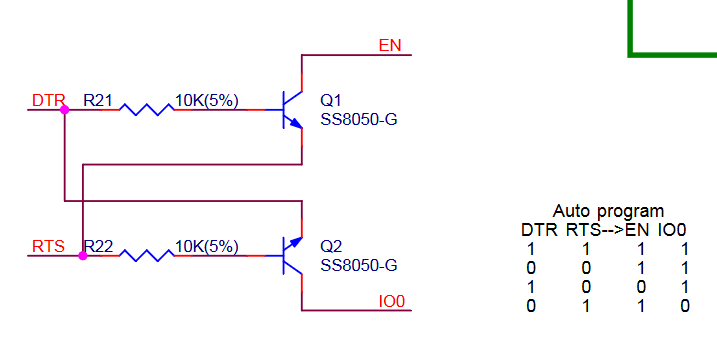
ESP32 hardware may have the RTS and DTR USB-to-UART converter connected to EN (enable) and GPIO0 of the ESP32 to the auto-reset. See other dev board schematic:
If DTR and RTS are wrongly driven it may cause EN or IO0 to be wrongly driven, and if EN has the wrong voltage (LOW or HIGH) on, that just disables the chip.
Makes sense. One thing that still is unclear for me:
Here is diagram of ESP32-CAM-MB.
When I set both DTR and RTS to 0 which sets both pins to 5v (RTD and DTR are active low) I am able to update firmware on my CAM without pushing bottons corresponding to reset and IO0. How is that achieved if RTS and DTR are both set to 0?
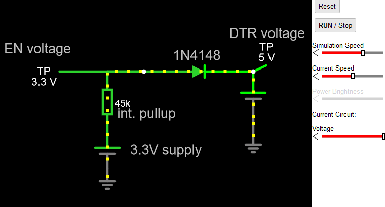
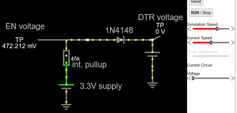
Well you can simulate this simple circuit with e.g. https://www.falstad.com/circuit/, also ref here.
DTR at 5V → EN at 3.3V.
DTR at 0V → EN at ~0V.
It’s a 1:1 logic mapping (LOW->LOW, HIGH->HIGH).
So if you want the chip to run you need to de-assert DTR (which causes DTR to be at the ‘high’ voltage).
Circuit simulation
1 Like
Thanks for taking time and providing these simulations. I think I was not clear. What I meant to say was that when DTR and RTS are both fixed at 5V through settings in platformio.ini, how can I put ESP32 into bootloader mode without pressing IO0 and RTS switches? That is what is happening now. I have DTR and RTS both set to 0 but I am still able to flash ESP32 without pressing any switches on it.
During flashing, esptool.py takes control of these lines and toggles the DTR and RTS pins. These are not statically controlled via monitor_rts and monitor_dtr, they only apply when PlatformIO’s serial monitor is open.
Ah, understood.
By the way I did not know about that circuit simulation tool. It is very cool. Thanks.
1 Like
