I have been trying to realize a project with the RP2040 chipset to drive some small SPI displays. During my testing phase, I have been using the Pi Pico board the set up most of the code. Now I have moved over to my own custom design PCB and the trouble begins.
Basically I have 2 displays in use, both with their own SPI interface. Compared against to Pi Pico board, I have changed some of the GPIO pins to archive a better PCB layout. So I updated my SW with the new pinout and loaded it onto my custom PCB. Display 1 works just a fine as with the Pi Pico board. Display 2 remains dark. Upon further invenstigation, I found out that non of the pins for the second display is showing any activity on the SPI lines. So I double checked my source code, the schematic, the layout and could not come up with any reason so far, as to why there is no activity on the second SPI at all.
Now before I start dismanteling my custom board setup and start making new wire harnesses to reconnect the Pi Pico board to the displays, I wanted to ask if anyone of you has encountered something similar.
The framework of Max seem to be deprecated, since the latest manual states the include raspberrypi for the platform. But from my understanding, this only supports the MBED core which does not work with my display library. I need the Earlephilhower core for this. Since this configuration has been working so far, I did not expect any problems be shuffeling some GPIO pins arround.
For sure I can do some more testing. I could compile the code using the Arduino IDE for example and check if the GPIO pins are working. Or I could write some basic code to toggle the pins manually the double check the custom PCB. But maybe I just did overlook something trivial you can point out for me?
Please post a (minimal) version fo your code. If you’re calling setSCK() etc on the right SPI objects like the documentation says, you should be perfectly fine.
And yes SPI does not work on every pin. You only have a few pin choices for hardware SPI. E.g., for SCK on SPI0 (exposed as SPI on Arduino), you have GP2, GP6, GP18 and GP22 available, etc.
Well the minimal code is basically calling the bus init function of the Arduino GFX library. Those are the settings that are working on the Pi Pico Board
As you can see I only did change a few pins affecting the SPI0 bus. In both cases those pins are assingned SPI0_CLK and SPI0_TX accoring to the datasheet.
Can you test with this minimal example, too? Change the display type as needed.
Another thing to note is that this GFX library wants to be a special boy and implements the Arduino_RPiPicoSPI class with direct calls to the Pico-SDK. This circumvent’s Arduino-Pico’s SPI class completely – so if you have other things in your sketch use the SPI and SPI1 object (which still have unmodified default SPI pin mappings), this will absolutely break since one will initialilze itself over the settings of the other one and they don’t coeexist well. Hence why the test with the minimal code is so important.
Note: In the above case, usage of the Arduino_HWSPI class will better things.
Thank you for your support Max, not only with my issue, but with the whole RP2040 - Platformio implementation.
I was able to locate the problem. In the end it was a manufacturing problem of my PCB. For what ever reason one of the Vias coming from power plane in the inner layers had no connection to that plane at all. This mean that one of the IOVDD pins was not supplied and therefore results in this failure.
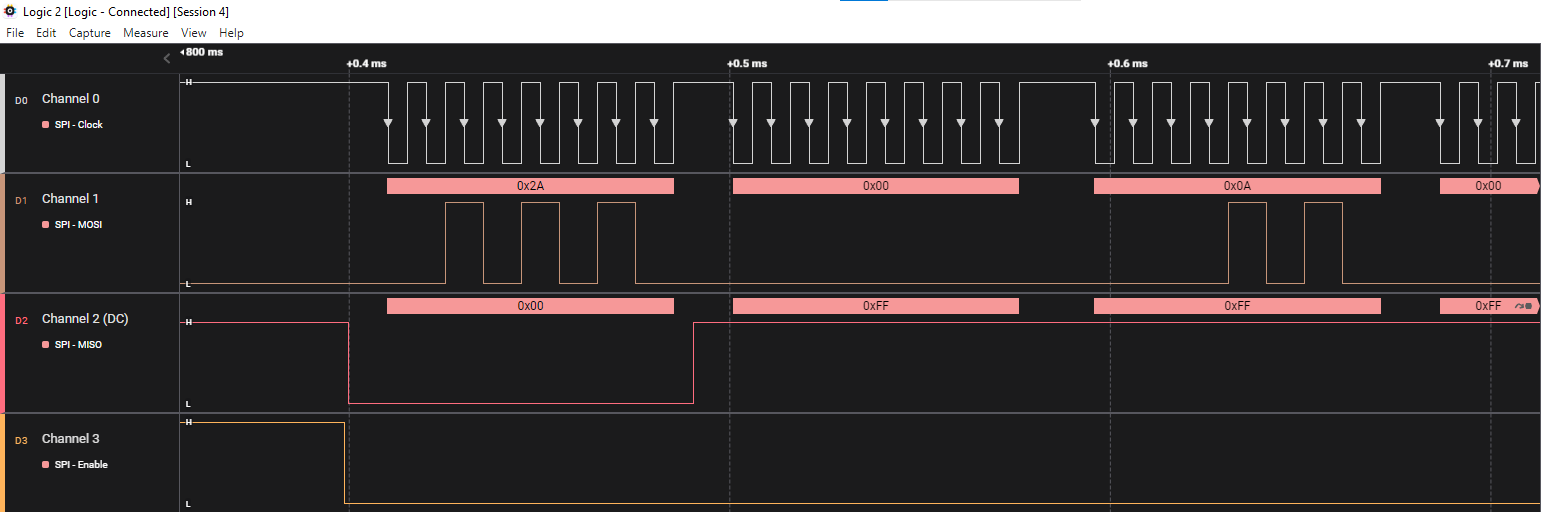
I was able to locate the problem after some testing. As Max wrote, the code should work. And yes, it was running on a Pi Pico board just fine. The interessting thing is that I could not see and levels on the GPIO pins of my DSP board at all. Hence I wrote some code just to set the pins by hand, and still could not measure any level changes at the pins. So I unplugged the DSP board from the rest of my Amp and checked it outside. Now I got 3V levels at my display pins. The heck? Reconnected the displays. Levels gone. Tested another display, not output again. So I swapped the IC, still the same result. Tested different pins, those are working fine. A though nut to crack. Until I was at a point where I checked supply voltages. And voila at one blocking cap there was not voltage. Checked layout, well it should be, checked PCB again, no voltage. So my guess is, that without the display the pins see no load and the voltage can be supplied chip internal via some parasitic elements. If you attach the display, current need to flow and that is too much for the chip internal structures to supply.
So in the end all that was needed as a fix is a small wire arround the IC to supply this IO Bank as well. I also checked the rest of my unpopulated PCBs 2 out of 5 have this production problem. So it was just my bad luck to pick on with the error for the first assembly.